Demagnetisation spikes on BLDC segment changes at low RPM

trialspower2

100 W
Joined
Dec 31, 2016
Messages
108
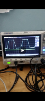
I am having issues with a voltage spike which is generated on each winding when it is released from zero volts as it enters its 'switched off' segment. This is worst at very low RPM, and gets smaller as the motor speed increases. The controller is running in synchronous rectification on a normal 6 step BLDC control.

When considering the commutation of a BLDC motor, each phase effectively does two segments high, one segment switched off, two segments low, one segment switched off. The spike always appears after the low period at low RPM under high current. The higher the current the higher the spike.

I have always had this issue, and have had to run higher gate resistor values to slow the switching rate. It was only earlier that I thought of something that may or may not help.

The spike appears in the region where only the high side winding stays switched on, as one phase is switch off from the low side while the other is switched on to the low side. Due to the deadtime my controller has, this effectively leaves a period where only one phase is connected and doesn't give the current anywhere to flow.

My thought today was, that maybe I should be switching the third phase low before releasing the phase which is already low. On a delta wound motor, this will then give a new path way though an extra phase to zero volts, preventing the energy going back up the phase being disconnected.

I realise this is hard to follow without any diagrams or event a proper explanation, I will try and put something together in the next day or so, but I thought someone might have had this before.
 
I have done some research on this, and it seems 150degree commutation exists. Has anyone had any experience with this?
 
Your thread title says "Demagnetisation spikes on BLDC segment changes at low RPM"...are you really seeing current spikes so high they demagnetize your magnets? (even enough to change the magnet strength would be pretty incredible, given the energy typically required to magnetize them in the first place).
 
I have maybe used the wrong terminology, the spike is due to demagnetization of the winding or basically when the winding is switched off.
 
If I'm understanding correctly, this is normal and just a result of the body diodes catching the current in the winding and regenerating it into the bus.

This basically has to happen since the decay constant if you were to just let it freewheel away would be tens or hundreds of milliseconds, probably far too slow for your needs.

If as a result you're significantly overshooting Vbat on your switch node you might have a body diode speed issue.

(Hopefully) attached is a screenshot of the spikes as you exit the low phase
 
Screenshot promised... Wouldn't attach before for some reason.

Further notes...
1) Demagnetisation is the correct term but it's referring to demagnetisation of the stator iron not the magnets.
2) ST micro BLDC firmware has some modification to help with this, I never studied it since I moved on to FOC before this every became an issue. I believe it basically enacted synchronous rectification of this pulse by turning on the correct FET during the conduction period. Your other option is to control your phase advance or add a period at the end of each sector which reduces the current to zero before transitioning sector.
 

Attachments

  • Screenshot_20230331-111828.png
    Screenshot_20230331-111828.png
    822.5 KB · Views: 7
Last edited:
Please see the image below, I have highlighted the spike in question with a black arrow. I guess this image is at around 100 battery amps, and 72V its just one I have found in my photos from the past.

Every speed controller failure I have had is caused by this spike, driving a 15470 outrunner extremely slowly at 150A battery current makes this spike big enough on 100V to exceed my 150V low side transistor rating.

I put larger gate resistor values on, this helps. But as we are running in synchronous, this makes the active freewheeling far less efficient.

My question is, would 150degree control help this spike (I see this exists, but can find very little about it on the net), or even connecting the floating phase to zero volts prior to release of this one. Rather than having that period where two phases are not connected. phase sequence2.jpg
 
120 com.png
When the spike occurs in the above, we are in a deadtime period where two phases are not connected to anything, while the third is on +

150 degree commutation below, We have some overlap, so we always have two phases connected at any one time.
150 com.png
 
I don't think the phase connection order will help since there's still a large inductance between the two phases. Maybe worth a try though.

This looks like a speed of MOSFET body diode issue, or high side parasitic inductance issue... The large current flowing through the low side as you switch off suddenly has to flow through the high side diode. Can you swap the high side FET for a faster one? Or add a high speed diode?

Can't find anything about 150 degree commutation, sorry. Just one paper and it seems ti drv10866 uses it. If going down that route though... Full Sinusoidal? You have an encoder...

This is caused by parasitic inductance I believe, but I cant optimize the design any further and I have tried. I have also got snubbers which I have tuned to reduce it as much as possible. Larger gate resistors is the only thing that will help, thats why I am looking for other options. If I got spikes on the PWM switching I would say the gate resistors are to small, but I dont. Its only on the segment changes, hence looking for a different commutation approach.

The issue at low RPM, battery current is 150amps at say 25% duty cycle, so phase current will be more like 600amps which doesnt like to be interrupted.

I agree that going full sinusoidal would solve this issue, but I dont think my PIC30F6015 is up to full sinusoidal, I kept with this IC as it is a 5V device and had all the functionality I needed....... well at least I thought I needed.

Yeah, I have sensors and an incremental encoder, there are things I can try. The 150degree commutation sounds interesting as it claims to increase torque, but then I think this was maybe done on a motor in star and not delta. However I can see a benefit in delta from full driving two windings for the periods of normally lowest torque which is effectively what it does. Not sure about the 3rd winding though which would effectively be shorted out during this period.

I can always start at 150degrees at low RPM and fade it out as the motor speed increases, once over 1000RPM or so, this issue goes away anyway.
 
I think you could run full Sinusoidal on that chip.

Might also be that although it looks like your duty is 25% and your current is about 600A.. it might be far higher at the end of a commutation block than at the start/middle as the phase back emf drops and your PID controller or whatever you have struggles to keep up.

That's the beauty of sinusoïdal, the current is so much better controlled at all times.

Another hack you could try is that in the last pwm period before you commute, just halve the PWM duty cycle, which will give it a chance to ramp down the current.

This is caused by parasitic inductance I believe, but I cant optimize the design any further and I have tried. I have also got snubbers which I have tuned to reduce it as much as possible. Larger gate resistors is the only thing that will help, thats why I am looking for other options. If I got spikes on the PWM switching I would say the gate resistors are to small, but I dont. Its only on the segment changes, hence looking for a different commutation approach.

The issue at low RPM, battery current is 150amps at say 25% duty cycle, so phase current will be more like 600amps which doesnt like to be interrupted.

I agree that going full sinusoidal would solve this issue, but I dont think my PIC30F6015 is up to full sinusoidal, I kept with this IC as it is a 5V device and had all the functionality I needed....... well at least I thought I needed.

Yeah, I have sensors and an incremental encoder, there are things I can try. The 150degree commutation sounds interesting as it claims to increase torque, but then I think this was maybe done on a motor in star and not delta. However I can see a benefit in delta from full driving two windings for the periods of normally lowest torque which is effectively what it does. Not sure about the 3rd winding though which would effectively be shorted out during this period.

I can always start at 150degrees at low RPM and fade it out as the motor speed increases, once over 1000RPM or so, this issue goes away anyway.
 
Last edited:
I only use a P control loop, its not massively sensitive and the adjustment value is limited.

I think you could run full Sinusoidal on that chip.

I had looked in the datasheet and wasnt sure it was possible, but after a search on google I have found that AN1017 contains a method on how to do it. It might be possible that I could take the relevant space vector modulation code and drop it into my current program. It seems to work with motor RPM calculated from the sensors rather than an encoder, so low speed might not be great unless I can use my encoder.

When considering my current options with pro and cons,

120 degree BLDC control
Good torque
Motor noise
Controller failures on segment changes at low RPM, or extra heat from larger gate resistors on the low side

150 degrees BLDC control (If it even works and what I read is at all true)
increased motor torque
better efficiency and reduced noise
might reduce segment change spikes

sinusoidal
less torque
quieter operation
increased efficiency
more stable current, so better for the controller
maybe more likely to be a reliable system


Does that sound about right?
 
That spike always seems to be there when using trapezoidal waveforms. It should be getting captured by the body diodes and circulated back to the main caps.
If your FETs have enough voltage rating, this shouldn't be a problem. If there is excessive inductance somewhere between the FETs and the main caps, I could imagine it could be destructively high.

Test motor_a.JPG

BEMF waveform - trapezoidal.JPG
 
Since this pulse is completely normal but the spike on top of it is unusually high compared to the normal pwm I wonder if it's indicative of another problem. Specifically I'm thinking either a glitch around commutation that results in a brief shoot through or that the actual phase current at that point is not 600A but closer to 1000+.

To your points above... Sinusoidal creates the most torque and with the last ripple of the options.
 
I think the flat top of the pulse is also higher than battery voltage maybe indicating there is a lot of energy. I think your probably right that the current is extremely high at this point which is causing my problem.

So based on this fact, I now see I need to go sinusodial or at least reduce the current as we are coming up to the end of the segment.

Without doing enough research and back ground reading my first thought is to zero my encoder count on hall A transition to high. I can then update the PWM based on the position of the motor at intervals until we do all 6 sequences and it gets re-sync'd on the next hall A high transition.

If my encoder count gets messed up, I will always have the right phases switch on, just not with the right duty cycle...

basically I put a percentage of the duty cycle required on each phase depending on the position of the motor? Does this still work with synchronous rectification?

My issue then, is how often to update the PWM, the 30F has limited function of the quadratic encoder interface, it only has interrupt on maxCount and not the facility to interrupt on a position match.

I think an update on every encoder pulse would be far to often, I think its a 1024ppr counting at x4. So then it should maybe be time based dependent on motor RPM?
 
The usual
I think the flat top of the pulse is also higher than battery voltage maybe indicating there is a lot of energy. I think your probably right that the current is extremely high at this point which is causing my problem.

So based on this fact, I now see I need to go sinusodial or at least reduce the current as we are coming up to the end of the segment.

Without doing enough research and back ground reading my first thought is to zero my encoder count on hall A transition to high. I can then update the PWM based on the position of the motor at intervals until we do all 6 sequences and it gets re-sync'd on the next hall A high transition.

If my encoder count gets messed up, I will always have the right phases switch on, just not with the right duty cycle...

basically I put a percentage of the duty cycle required on each phase depending on the position of the motor? Does this still work with synchronous rectification?

My issue then, is how often to update the PWM, the 30F has limited function of the quadratic encoder interface, it only has interrupt on maxCount and not the facility to interrupt on a position match.

I think an update on every encoder pulse would be far to often, I think its a 1024ppr counting at x4. So then it should maybe be time based dependent on motor RPM?
The usual way to do this is to generate an interrupt once per pwm period and do the calculation for the next period. There's no need to update the PWM any faster than this.

With your micro, provided your code is compiling sensibly (you need to check you are not accidentally bumping yourself into libraries for dealing with floating point or worse doubles!) you should easily be able to achieve this update rate. Looks like you're running 16khz and you're able to run 40MHz+ CPU core so you have several thousand clock cycles to do the update.

It's very easy to have the compiler absolutely wreck your program efficiency with the wrong settings or mixing up your data types.

My other observation from your scope shot above is that you're commuting the sector quite late. In general it's better to commute slightly early, since that means the current can ramp up faster during a lower BEMF (implicit field weakening and MTPA by phase advance). If you
Commute late, the ramp up of current occurs at the highest BEMF so is slower and then the ramp up continues and gets more aggressive as the BEMF on that phase drops - as you exit the sector.

Effectively...
Commuting early-> optimal up to a point, some degree of FW and MTPA
Commuting exactly in phase -> slightly sub optimal, but stable
Commuting late-> your motor is a resistor and you get huge current spikes.
 
Last edited:
What are the indicators on the scope shot that commutation is to early? My hall sensors are adjustable, and I typically would set them for lowest no load current which by the sounds of it might not be the best approach....

When operating sinusoidal, can I keep my PWM outputs in complementary? This is required for low RPM to keep the bootstrap capacitors charged. I have also written my speed control equation to operate with the regen under this mode. I need the motor to brake like it does now on BLDC control with synchronous rectification.

I have downloaded the source code for microchips application note, however it seems to have been updated for the PIC33, rather than the PIC30F. But I can use the bulk of it, the sine lookup table is an array of integers. It also uses compiler built in functions for fast math operations. I just need to get my head around how it all works.

The microchip example has 60RPM minimum, so I will need to do some work to get it working as I need.
I guess using my encoder to count one 360degree cycle is the best route, can easily work out the angle for the correct PWM duty cycle from this. I am thinking on power up, until the sequence start hall sensor is hit, I will have to run in trapezium control.
Sinusoidal commutation needs the complimentary PWM, it's not optional.

The indication on your scope shot that you're commuting too late is that the undriven phase sector on the left shows the BEMF flattening out whereas there's not as much/no flat section on the undriven phase to the right.
 
I have been doing some reading on Sinusoidal control and I think I am getting my head around it. The microchip application note does pretty much what I need, I am just trying to work out exactly what it all does.

While I understand what the following lines of code do, I am not sure how they achieve the required result;

// in the PTPER register.
tpwm = PTPER << 1;

// Limit volts input to avoid overmodulation.
if(volts > VOLTS_LIMIT) volts = VOLTS_LIMIT;

if(angle < VECTOR2)
{
angle2 = angle - VECTOR1; // Reference SVM angle to the current
// sector
angle1 = SIXTY_DEG - angle2; // Calculate second angle referenced to
// sector

t1 = sinetable[(unsigned char)(angle1 >> 6)]; // Look up values from
// table.
t2 = sinetable[(unsigned char)(angle2 >> 6)];

// Scale t1 to by the volts variable.
t1 = ((long)t1*(long)volts) >> 15;
// Scale t1 for the duty cycle range.
t1 = ((long)t1*(long)tpwm) >> 15;
// Scale t2 time
t2 = ((long)t2*(long)volts) >> 15;
t2 = ((long)t2*(long)tpwm) >> 15;

half_t0 = (tpwm - t1 - t2) >> 1; // Calculate half_t0 null time from
// period and t1,t2

// Calculate duty cycles for Sector 1 (0 - 59 degrees)
PDC1 = t1 + t2 + half_t0;
PDC2 = t2 + half_t0;
PDC3 = half_t0;
}


So we lookup the values of t1 and t2 based on the current motor angle (this is worked out depending on what vector we are in)

The values in the lookup table range from 0 to 28377 for t1/t2

The maximum value for volts is 28300. I am not sure why this number was chosen.

The value of tpwm is the value for the maximum duty cycle (100% duty cycle minus deadtime)

To scale the result to the pwm duty cycle range I would have thought you would have to divide, but its done using right shifts. I understand this halfs the number each shift, but I dont know how it works in this usage.
 
I have been doing some reading on Sinusoidal control and I think I am getting my head around it. The microchip application note does pretty much what I need, I am just trying to work out exactly what it all does.

While I understand what the following lines of code do, I am not sure how they achieve the required result;


So we lookup the values of t1 and t2 based on the current motor angle (this is worked out depending on what vector we are in)

The values in the lookup table range from 0 to 28377 for t1/t2

The maximum value for volts is 28300. I am not sure why this number was chosen.

The value of tpwm is the value for the maximum duty cycle (100% duty cycle minus deadtime)

To scale the result to the pwm duty cycle range I would have thought you would have to divide, but its done using right shifts. I understand this halfs the number each shift, but I dont know how it works in this usage.
28300 is int16_tmax*(sqrt3/2). This is the max value the method can write before the sin wave exceeds the max PWM value.

Basically everything they've done there is to make a computationally efficient way of converting a voltage and angle into a sin wave. Since your MCU cannot handle floating point, they scale all the values to use the range of int16(short) and int32_t (long).

When you have to regularly divide by a number that doesn't change, the most computationally efficient way to do it on an MCU like yours is to multiply by a number you calculate in advance and then divide by a power of 2 (right shift). Hence the >>15s.
 
ok, cheers

so currently in my firmware, I take my equation output and scale it to my PWM duty cycle which roughly 100 - 3500 )(100 being the count which overcomes the deadtime and starts to give an output)

if I do the same, but scale it between 0 - 28300 initally and then feed it into the microchip code along with the encoder angle it should work? I presume like in my code now, zero will not be correct due to deadtime and it might be a somewhat higher number before the motor beings to turn? I think you can get PWM anomalies if the duty cycle is less than twice the deadtime.

currently I use a PWM count below 100 to regen brake (controlled by the brake lever) and set it to 0 if the RPM is low enough to lock up the motor as much as possible. (probably only required for trials), I dont know if this will work the same in sinusoidal
 
Back
Top