
Alan B
100 GW
Some folks have had problems with Battery Management Systems (BMS) causing damage to their battery packs. In some cases this has lead to a very negative response to all BMS electronics. So I am considering what it would take to make a reliable cell monitoring system primarily focussed on the essential on-board ebike systems.
Gathering more accurate data about actual BMS failures was suggested below and is being handled in another thread. This design is evolving as the issues are identified and the design matures. Here is the data gathering thread:
http://www.endless-sphere.com/forums/viewtopic.php?f=5&t=22382
One consideration in maximizing reliability is to minimize the electronics on the bike. This argues for charging and balancing off-bike. Failures in the balancing circuits often cause the associated cell to be overdischarged. All that really must remain on-bike is monitoring cells for informational purposes and for low voltage shutdown. So this design splits the BMS into on-bike cell monitoring and protection, and off-bike charging and balancing.
So how simple and reliable can the on-bike cell monitoring and protection system be made?
The traditional circuits commonly found for this use a voltage monitor chip (such as a TC54) and an optical isolator per cell. A zener may be added to provide some protection for the somewhat fragile voltage monitor part (the fact that this was done indicates there was experience with damage to the units from connecting in the wrong order). This circuit will not work below some voltage around 1.5 volts due to the optical isolator LED. The low voltage cutout threshold of this design is not easily adjustable. If the voltage monitor chip fails (and they are susceptible to too much voltage from incorrect wiring, spikes or ESD) there is no indication that a cell is no longer protected. It is difficult to test the individual undervoltage circuits. There is no overvoltage protection.
What are the risks to the system? The batteries have potentially significant transients, especially during connect cycles where high currents flow to charge the controller capacitors. Connecting the input wires to the wrong cell junction presents another challenge to the electronics. The voltage monitor chips have a fairly limited input voltage range. ESD from the user during connecting, or touching the circuit board is another issue. The initial wiring process presents a significant risk of incorrect connections as well. The connect/disconnect cycle presents risks such as random order make-break of the connectors.
Another problem is protection when the bike is not in use (or when there is a failure in the ebrake circuit). Sending a signal to the ebrake line doesn't work when the bike is stored as no one will notice it.
The question is, can we do better without getting too costly or complicated?
So here are some requirements (version 0.7):
1) Low cell voltage triggers optical isolator to ebrake (same functionality as standard circuits).
2) Robust against voltage spikes and connecting to the wrong cell or connecting in any order.
3) Self detection of correct wiring and operation, providing visual indication of proper operation.
4) Continue to operate if any one or two cells go to 0 volts. (perhaps expand this to all but 2 cells at 0V?)
5) Protect pack against overdischarge even when ebike is not in use.
6) Consume less than half of 5AH per year if left plugged in. (285 uA)
7) Avoid failure modes that "drain" the pack. Semiconductors that short should not draw the pack down.
8) Accurate enough to catch the 1V plus transition from "normal" cell voltage to "nearly empty", so 0.05 volt.
9) Have a low parts count (and a low cost).
10) Be easily unplugged from the pack for extended storage.
11) Use robust wiring and connectors.
12) Avoid high currents running through the monitor.
13) Components should be readily available.
The common designs based on the TC54 voltage monitor fail to meet requirements 2,3,4,5,9. These designs can be improved but it is unlikely that all requirements can be met, and the parts count is already getting quite high.
The CellLogs fail to meet requirement 6 (and require external circuitry to meet 1). There is at least one report of a CellLog getting "hung" and failing to meet requirement 3.
So how can we meet these requirements?
I sketched out a design for an 8S cell monitoring based on a single chip microcontroller that appears to meet these requirements. This requires:
8 analog inputs (for 8 cell monitoring)
1 output for optical isolator to ebrake
1 output for piezoelectric beeper (to chirp like smoke alarm when battery gets low in case it is not on the bike)
4 pins for programming
2-4 pins for ground and vcc
Why 8 cells? The common ADCs on these parts are 10 bits, or 1 part in 1024. At 35V full scale that will give 35 millivolt resolution. Going higher in cell count will reduce the resolution and make it difficult to meet requirement 8. (Also my pack is 16S in two 8S sections)
I did a parts search and find the Atmel ATTiny261 (20 pins) meets these requirements (with 2 pins for future communications). In 25 quantity this part is only $1.82!
So what does it take to protect the micro? The ADC inputs are the most at-risk by virtue of coming from offboard. The ADC has a 1V full scale range, so a divider network is required to bring the +30V of the 8S pack into that range. A capacitor to provide filtering also provides transient protection, and the impedance of the divider network controls the current as it scales the voltage. The micro has diode protection internally as well. Since the resistive divider is reducing 30V to 1V and the chip can handle 5V the transient would have to exceed 150V to even begin to trigger the protection diodes.
The voltage regulator is a type intended for battery operation and well protected with such features as reverse polarity protection. It is augmented with capacitors and series surge limiting resistor.
Power consumption can be very low. Setting the resistance of the voltage dividers high helps minimize current there. The micro can be put into sleep on a timer to minimize CPU power consumption. The regulator is an ultra low power type with very low idle current.
If an ADC becomes damaged it "fails safe" as the reading won't fall into the correct valid range, and the beeper/ebrake will indicate a problem. So it can self check.
A reverse bias zener diode across the optical isolator output protects it against reverse voltage and locks out the controller until it is polarized correctly.
An onboard LED that periodically blinks (again taking after smoke alarms providing an indication at very low power consumption) indicates proper CPU operation. This can be visually checked each time the pack is charged to insure the monitoring is working.
The watchdog timer in the CPU reboots if the program gets "hung" and fails to respond with the timer's limit.
The CPU Brownout detector insures that more than 2 cells at 0V will be indicated by the lack of blinking on the operating LED, and that the CPU won't try to operate when the voltage is too low for reliable functionality.
If a cell (or two) goes to 0V there is still enough voltage to power the monitor, so it will continue to disable the controller and chirp the piezo. This is an improvement over the traditional design that stops protecting when a cell falls below about 1.5V. Most traditional designs also do not have the audible alarm.
There are two types of connections to the battery pack in this design. One is for providing power to the Cell Monitor. The other is to sample the pack voltage at each cell juncture. Sampling the pack voltage is done through a resistive voltage divider. A failure of the silicon in the micro could at worst be a short of the 1V portion of the 30V divider and would not appreciably increase the current. The regulator failure modes, especially a short in the regulator present a more significant risk to the battery. If the regulator fails the LED will stop blinking, so it might be noticed. Choice of the fuse and series impedance for the regulator will be important and will be reviewed in this light as the design progresses.
A good connector is important, perhaps a DB9M on the board, and use commercial DB9 cables cut and re-terminated to the batteries for the other side. For even more protection against shorts and KFF (kentucky fried fingers) small fuses can be installed at the battery. This same connector can be used by the charge balancing system off-bike.
Installing clear heatshrink over the PCB protects it from various short circuit problems while allowing visibility of the LEDs. It is more serviceable than a conformal coating (though not as waterproof). Protection from water should be handled by the system packaging.
The remaining ESD risk is through the programming pins. These pins are less protected. Once programmed these pins should be covered with the heatshrink or a connector placed on them to avoid direct contact. A programming fixture could be used that would avoid installing the pins on the board. Just pushing the connector into the holes is generally adequate for the programming cycle of a few seconds. Program verification insures that it is properly programmed.
So we have a basic 8 cell monitor in three chips (instead of the usual 12-16 chip solutions that have no self-checking). For higher cell counts use more of the 8 cell modules. For lower cell counts (or remainders) adjust the software to ignore the unused input channels. With a bit more software and a couple more optical isolators it could even read out individual cell voltages to a remote display, but I will leave that for an upgrade... Though I will arrange the micro pinout so the serial I/O pins are available. The final pinout of the schematic will occur with the PCB layout, flexibility helps in the layout process.
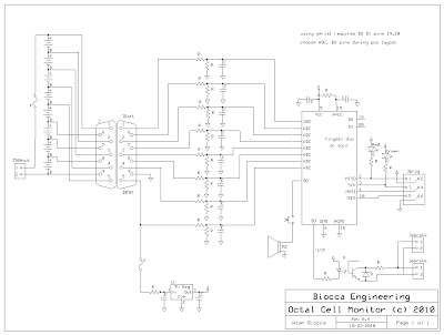
Link to larger schematic:
http://picasaweb.google.com/lh/photo/4CXPkVY13XaJinAj1zZ7WIPSvVPFxOvt9gQSg1eZ7bg?feat=directlink
Software
Risks from software errors can be minimized by keeping it simple, testing, and making the sourcecode public for review by others.
Requirements
Essential
Wakeup on Watchdog Timer periodically
Perform self tests
Read cell voltages, average, apply calibration factor
Difference, Compare against window (low, high)
If all selftests and voltages okay then periodically blink green LED
If out of range then set ebrake and squeak piezo and blink red LED
Configure for low power and go to sleep
Nice to Have
Test for "motor running" and adjust thresholds, sample less often, conserve power
Design architectures to review:
TC54 power on reset voltage monitor chip
MAX11068,MAX11080 hi cell count monitor/management chips
DS2726 cell monitor/balancing chip
LTC6802 battery management chip
ATTINY261 microprocessor chip
I am not certain at this point if I will build this. If a clearly worthwhile design emerges from the process and there is interest, perhaps a collaborative build might be done. My time is limited, perhaps someone wants to help with pcb layout and production. It could be a through-hole kit. It could be surface mount and very small. I can handle the software. Programmers for this chip start at about $15 so that's not an impediment for those who want to play with the code or make their own.
Comments on this evolving design (and others that meet these requirements) are welcome in this thread.
Thanks for your input!
Gathering more accurate data about actual BMS failures was suggested below and is being handled in another thread. This design is evolving as the issues are identified and the design matures. Here is the data gathering thread:
http://www.endless-sphere.com/forums/viewtopic.php?f=5&t=22382
One consideration in maximizing reliability is to minimize the electronics on the bike. This argues for charging and balancing off-bike. Failures in the balancing circuits often cause the associated cell to be overdischarged. All that really must remain on-bike is monitoring cells for informational purposes and for low voltage shutdown. So this design splits the BMS into on-bike cell monitoring and protection, and off-bike charging and balancing.
So how simple and reliable can the on-bike cell monitoring and protection system be made?
The traditional circuits commonly found for this use a voltage monitor chip (such as a TC54) and an optical isolator per cell. A zener may be added to provide some protection for the somewhat fragile voltage monitor part (the fact that this was done indicates there was experience with damage to the units from connecting in the wrong order). This circuit will not work below some voltage around 1.5 volts due to the optical isolator LED. The low voltage cutout threshold of this design is not easily adjustable. If the voltage monitor chip fails (and they are susceptible to too much voltage from incorrect wiring, spikes or ESD) there is no indication that a cell is no longer protected. It is difficult to test the individual undervoltage circuits. There is no overvoltage protection.
What are the risks to the system? The batteries have potentially significant transients, especially during connect cycles where high currents flow to charge the controller capacitors. Connecting the input wires to the wrong cell junction presents another challenge to the electronics. The voltage monitor chips have a fairly limited input voltage range. ESD from the user during connecting, or touching the circuit board is another issue. The initial wiring process presents a significant risk of incorrect connections as well. The connect/disconnect cycle presents risks such as random order make-break of the connectors.
Another problem is protection when the bike is not in use (or when there is a failure in the ebrake circuit). Sending a signal to the ebrake line doesn't work when the bike is stored as no one will notice it.
The question is, can we do better without getting too costly or complicated?
So here are some requirements (version 0.7):
1) Low cell voltage triggers optical isolator to ebrake (same functionality as standard circuits).
2) Robust against voltage spikes and connecting to the wrong cell or connecting in any order.
3) Self detection of correct wiring and operation, providing visual indication of proper operation.
4) Continue to operate if any one or two cells go to 0 volts. (perhaps expand this to all but 2 cells at 0V?)
5) Protect pack against overdischarge even when ebike is not in use.
6) Consume less than half of 5AH per year if left plugged in. (285 uA)
7) Avoid failure modes that "drain" the pack. Semiconductors that short should not draw the pack down.
8) Accurate enough to catch the 1V plus transition from "normal" cell voltage to "nearly empty", so 0.05 volt.
9) Have a low parts count (and a low cost).
10) Be easily unplugged from the pack for extended storage.
11) Use robust wiring and connectors.
12) Avoid high currents running through the monitor.
13) Components should be readily available.
The common designs based on the TC54 voltage monitor fail to meet requirements 2,3,4,5,9. These designs can be improved but it is unlikely that all requirements can be met, and the parts count is already getting quite high.
The CellLogs fail to meet requirement 6 (and require external circuitry to meet 1). There is at least one report of a CellLog getting "hung" and failing to meet requirement 3.
So how can we meet these requirements?
I sketched out a design for an 8S cell monitoring based on a single chip microcontroller that appears to meet these requirements. This requires:
8 analog inputs (for 8 cell monitoring)
1 output for optical isolator to ebrake
1 output for piezoelectric beeper (to chirp like smoke alarm when battery gets low in case it is not on the bike)
4 pins for programming
2-4 pins for ground and vcc
Why 8 cells? The common ADCs on these parts are 10 bits, or 1 part in 1024. At 35V full scale that will give 35 millivolt resolution. Going higher in cell count will reduce the resolution and make it difficult to meet requirement 8. (Also my pack is 16S in two 8S sections)
I did a parts search and find the Atmel ATTiny261 (20 pins) meets these requirements (with 2 pins for future communications). In 25 quantity this part is only $1.82!
So what does it take to protect the micro? The ADC inputs are the most at-risk by virtue of coming from offboard. The ADC has a 1V full scale range, so a divider network is required to bring the +30V of the 8S pack into that range. A capacitor to provide filtering also provides transient protection, and the impedance of the divider network controls the current as it scales the voltage. The micro has diode protection internally as well. Since the resistive divider is reducing 30V to 1V and the chip can handle 5V the transient would have to exceed 150V to even begin to trigger the protection diodes.
The voltage regulator is a type intended for battery operation and well protected with such features as reverse polarity protection. It is augmented with capacitors and series surge limiting resistor.
Power consumption can be very low. Setting the resistance of the voltage dividers high helps minimize current there. The micro can be put into sleep on a timer to minimize CPU power consumption. The regulator is an ultra low power type with very low idle current.
If an ADC becomes damaged it "fails safe" as the reading won't fall into the correct valid range, and the beeper/ebrake will indicate a problem. So it can self check.
A reverse bias zener diode across the optical isolator output protects it against reverse voltage and locks out the controller until it is polarized correctly.
An onboard LED that periodically blinks (again taking after smoke alarms providing an indication at very low power consumption) indicates proper CPU operation. This can be visually checked each time the pack is charged to insure the monitoring is working.
The watchdog timer in the CPU reboots if the program gets "hung" and fails to respond with the timer's limit.
The CPU Brownout detector insures that more than 2 cells at 0V will be indicated by the lack of blinking on the operating LED, and that the CPU won't try to operate when the voltage is too low for reliable functionality.
If a cell (or two) goes to 0V there is still enough voltage to power the monitor, so it will continue to disable the controller and chirp the piezo. This is an improvement over the traditional design that stops protecting when a cell falls below about 1.5V. Most traditional designs also do not have the audible alarm.
There are two types of connections to the battery pack in this design. One is for providing power to the Cell Monitor. The other is to sample the pack voltage at each cell juncture. Sampling the pack voltage is done through a resistive voltage divider. A failure of the silicon in the micro could at worst be a short of the 1V portion of the 30V divider and would not appreciably increase the current. The regulator failure modes, especially a short in the regulator present a more significant risk to the battery. If the regulator fails the LED will stop blinking, so it might be noticed. Choice of the fuse and series impedance for the regulator will be important and will be reviewed in this light as the design progresses.
A good connector is important, perhaps a DB9M on the board, and use commercial DB9 cables cut and re-terminated to the batteries for the other side. For even more protection against shorts and KFF (kentucky fried fingers) small fuses can be installed at the battery. This same connector can be used by the charge balancing system off-bike.
Installing clear heatshrink over the PCB protects it from various short circuit problems while allowing visibility of the LEDs. It is more serviceable than a conformal coating (though not as waterproof). Protection from water should be handled by the system packaging.
The remaining ESD risk is through the programming pins. These pins are less protected. Once programmed these pins should be covered with the heatshrink or a connector placed on them to avoid direct contact. A programming fixture could be used that would avoid installing the pins on the board. Just pushing the connector into the holes is generally adequate for the programming cycle of a few seconds. Program verification insures that it is properly programmed.
So we have a basic 8 cell monitor in three chips (instead of the usual 12-16 chip solutions that have no self-checking). For higher cell counts use more of the 8 cell modules. For lower cell counts (or remainders) adjust the software to ignore the unused input channels. With a bit more software and a couple more optical isolators it could even read out individual cell voltages to a remote display, but I will leave that for an upgrade... Though I will arrange the micro pinout so the serial I/O pins are available. The final pinout of the schematic will occur with the PCB layout, flexibility helps in the layout process.
Link to larger schematic:
http://picasaweb.google.com/lh/photo/4CXPkVY13XaJinAj1zZ7WIPSvVPFxOvt9gQSg1eZ7bg?feat=directlink
Software
Risks from software errors can be minimized by keeping it simple, testing, and making the sourcecode public for review by others.
Requirements
Essential
Wakeup on Watchdog Timer periodically
Perform self tests
Read cell voltages, average, apply calibration factor
Difference, Compare against window (low, high)
If all selftests and voltages okay then periodically blink green LED
If out of range then set ebrake and squeak piezo and blink red LED
Configure for low power and go to sleep
Nice to Have
Test for "motor running" and adjust thresholds, sample less often, conserve power
Design architectures to review:
TC54 power on reset voltage monitor chip
MAX11068,MAX11080 hi cell count monitor/management chips
DS2726 cell monitor/balancing chip
LTC6802 battery management chip
ATTINY261 microprocessor chip
I am not certain at this point if I will build this. If a clearly worthwhile design emerges from the process and there is interest, perhaps a collaborative build might be done. My time is limited, perhaps someone wants to help with pcb layout and production. It could be a through-hole kit. It could be surface mount and very small. I can handle the software. Programmers for this chip start at about $15 so that's not an impediment for those who want to play with the code or make their own.
Comments on this evolving design (and others that meet these requirements) are welcome in this thread.
Thanks for your input!
 ) and it is quite a powerful tool to design out known failure modes in systems.