
Kingfish
100 MW
DIY: My Incredibly Ghetto Wheel Balancing Rim & Disc Brake Rotor Truing System
Greetings –
Actually this apparatus might contain fewer parts than the count of words in the title. :lol:
Goal:
Need a fixture to hold the bike frame up at the wheel so we can make adjustments. Prefer the fixture to be inexpensive since chances are we only need to make these adjustments when we change the tires or the brakes.
Solution:
Had some timber lying about and figured that with a few fasteners, I could cobble something together for less than $10. It's not pretty, but it's also a whole lot less than what's out there in the market – and you can build it yourself!
The apparatus is rotated 180° for the Front, however the terminology (Left & Right) are in reference to when it is in the Rear position.
Features:
This is pretty easy to use: Just place it on the ground, throw a counterweight on it, then roll the bike forward or back and lift it into place. Originally designed to solve the alignment problem with the rear wheel, and later I determined that the dishing was not sufficient (and was creating the pesky rubbing that was so annoying on my road trip to Cali).
Once all that rubbing business was settled I attacked the squeaking disc rotor which was tedious to adjust, and I took my time with it – taking a break every now and then. Finally the rear wheel was fixed and I took a Christmas holiday.
Resolved to fix the Front wheel squeaking in the New Year, and had to make some slight adjustments (ala shims) to adapt the device for the front. Again, this was quite tedious, and in the process I discovered that the left front hub cover is warped slightly… about 3mm. I fixed the rubbing issue by taking a flat nail file (about 2mm thick) and stuffing it between the caliper and the cover at the point of most interference and was able to realign the caliper away from the hub. Then I could actually true the rotor and eliminate the pesky squeaking.
It’s so surprising how much drag there was before, and now the wheels spin freely and I’m wonder how much more distance I’ll gain. I can hardly wait until the-3-days-of-summer to try another speed test
Whatcha think? Should I file for a patent? Remember – you heard it first right here on ES!
Cheers, KF
Greetings –
Actually this apparatus might contain fewer parts than the count of words in the title. :lol:
Goal:
Need a fixture to hold the bike frame up at the wheel so we can make adjustments. Prefer the fixture to be inexpensive since chances are we only need to make these adjustments when we change the tires or the brakes.
Solution:
Had some timber lying about and figured that with a few fasteners, I could cobble something together for less than $10. It's not pretty, but it's also a whole lot less than what's out there in the market – and you can build it yourself!
The apparatus is rotated 180° for the Front, however the terminology (Left & Right) are in reference to when it is in the Rear position.
Features:
- Allows the wheel to spin freely
- Facilitates alignment (especially important for rear hubs)
- Allows for proper dishing whilst in situ
- Facilitates truing of both rim and disc rotor
- And allows for proper alignment of braking hardware
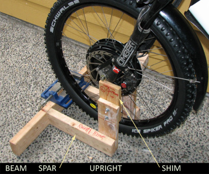
- Lateral Beam, 2x4, length greater than 16", Qty-1.
- Lateral Spar, 2x4, length slightly longer than tire radius: Example - 14" works well for 26" wheel. Qty-2.
- Upright Right, 1x4, length about 12.5" (See Notes)
- Upright Left, 1x4, length about 14.5" (See Notes)
- Shim Right, 1x4, length about 7.5" (fastened when required)
- Shim Left, 2x4, length 6" (a simple block of wood)
- ¼" Flat Washer, Qty-18
- ¼" x 2" Hex-Head Wood Screw, Qty-6
- ¼" x 4" Hex-Head Wood Screw, Qty-4
- ¼-20 x 2" UNC Hex-Head Bolt, Qty-4
- ¼-20 UNC-2B Wingnut, Qty-4
- I prefer using flat washers to spread the load; there's one for every bearing head and nut.
- Use two 4" wood screws secure each Lateral Spar to the Lateral Beam: Clamp the Spar to the Beam. Predrill a clearance hole through the Lateral Beam using a ¼" bit, and follow using a smaller bit into the Spar; this will allow faster construction and prevent splitting.
- Use three 2" wood screws to secure the Uprights to the Spar following the same method employed to fasten the Spars to the beam.
- Fasteners should cost about $7.50, and the pieces of wood are scraps that I found at construction sites.
- The length for the Uprights are determined by the radius of the largest wheel + an inch or two for clearance.
- The length on the Right Upright is shorter because it rests against the derailleur which is slightly lower than the axle.
- Special Note: My rear wheel is 24" and the front is 26", therefore I need to shim the apparatus for use on the front when it is rotated 180°; if your wheels are the same size, you will only need the right shim and thus a 2x4 block of wood seems to work perfectly. The Right Shim is mounted to the Right Upright using two 2" long bolts and wingnuts (as displayed in the image above). The offset should be measured with some care; it's not exact science but if it's off by too much the bike will wander off the mount.
- The lateral Spars can be made longer to prevent the apparatus from tipping. Otherwise a counterweight may be required.
- As previously stated, extending the lateral spars would prevent tipping.
- A fastener to hold the left shim (simple block of wood) in place
This is pretty easy to use: Just place it on the ground, throw a counterweight on it, then roll the bike forward or back and lift it into place. Originally designed to solve the alignment problem with the rear wheel, and later I determined that the dishing was not sufficient (and was creating the pesky rubbing that was so annoying on my road trip to Cali).
Once all that rubbing business was settled I attacked the squeaking disc rotor which was tedious to adjust, and I took my time with it – taking a break every now and then. Finally the rear wheel was fixed and I took a Christmas holiday.
Resolved to fix the Front wheel squeaking in the New Year, and had to make some slight adjustments (ala shims) to adapt the device for the front. Again, this was quite tedious, and in the process I discovered that the left front hub cover is warped slightly… about 3mm. I fixed the rubbing issue by taking a flat nail file (about 2mm thick) and stuffing it between the caliper and the cover at the point of most interference and was able to realign the caliper away from the hub. Then I could actually true the rotor and eliminate the pesky squeaking.
It’s so surprising how much drag there was before, and now the wheels spin freely and I’m wonder how much more distance I’ll gain. I can hardly wait until the-3-days-of-summer to try another speed test
Whatcha think? Should I file for a patent? Remember – you heard it first right here on ES!
Cheers, KF