E-bike gauge

agniusm

1 MW
Joined
Apr 16, 2011
Messages
2,579
Location
Lithuania, Zarasai
Hi, I have little experience in electronics and even a lot less in programming so this part is the hardest but never the less i would like to try and build myself ebike gauge.
i will be using three sensors, first for voltage, voltage divider, second - current sensor, will be using 100A allegro bidirectional sensor and third, hall effect sensor from hub motor.
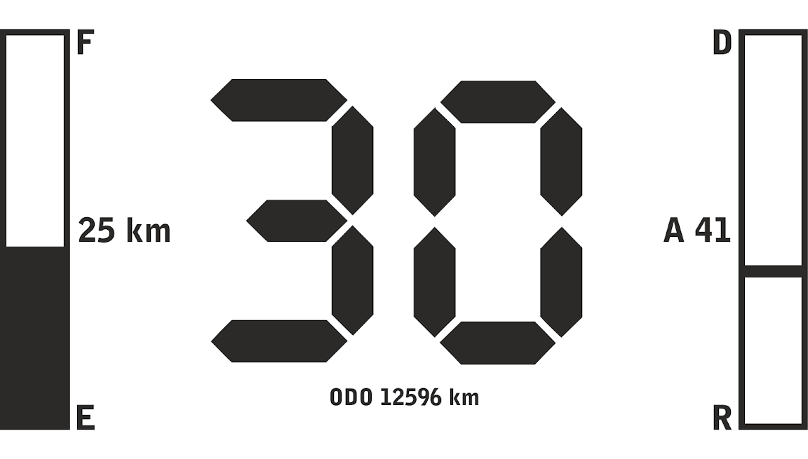
i would like to have 4 values to be displayed:
Kilometers left on battery (Which would be calculated on averaging the draw);
Power draw in amps or watts as well as power put in to the battery on regeneration; (Half gimmick half useful for adjusting driving style)
Speed;
Odometer with stored distance in eeprom.
i came up with this layout:
meter.png


My screen is 128x64 transflective with white backlight:
https://www.youtube.com/watch?v=vBfRDwSbFQg
i chose this LCD for its visibility in direct sunlight:
[youtube]ZLQiJjm7JbI[/youtube]

The driver is ST7565P:
$T2eC16d,!zoE9s5ngHi5BR)bG5579!~~60_3.JPG

In u8glib using:
U8GLIB_64128N u8g(13, 11, 10, 9, 8);
Need help with programming the LCD to display correct info and tieing values from input to display output. It could be separate components and i think i could put all together and arrange as i require if there are some comments in the code:)
greatly appreciated.
So far i have implemented font i would like to use:
20130720_151211

After some correction:
20130720_155517

and another font just to have few:
20130720_165541


Here is speed imitation animation:
[youtube]15tuK5SUqnM[/youtube]

Basically i am after simple, clean, sleek, classy cycle computer with basic functionality implemented, open source for end user. Perhaps i am over my head with this but one must try:)
I would like some help from community with getting this device done which then be available to buy and modify ;)
I would like it to be milled from solid block aluminum, phone like tinted glass over it, 2 buttons for later implementation.
promising nothing yet but it might end up something.
P.S. Hope this in the right section of the forum.
 
This what i gathered for voltage divider:
Code:
#include <LiquidCrystal.h>


LiquidCrystal lcd(7, 8, 9, 10, 11, 12);

int screen_backlight = 13;                       
float voltage_battery1 = 0.0;                    //voltage from pin A0
float voltage_reference1 = 0.0;                  //reference voltage on the arduino 5V-rail
float voltage_battery2 = 0.0;                    //voltage from pin A0
float voltage_reference2 = 0.0;                  //reference voltage on the arduino 5V-rail
float voltage_divider = (6780.0+2720.0)/2720.0;  //((R1+R2)/R2)*voltage for voltage divider before pin A0

void setup() {
  pinMode(screen_backlight, OUTPUT);       //LCD Setup
  digitalWrite(screen_backlight, HIGH);    // turn backlight on. Replace 'HIGH' with 'LOW' to turn it off.
  lcd.begin(20,4);                         // columns, rows.  use 16,2 for a 16x2 LCD, etc.
  lcd.clear();                             // start with a blank screen
}

//method 1
int getBandgap(void) // Returns actual value of Vcc  (x100)
    {    
      #if defined(__AVR_ATmega1280__) || defined(__AVR_ATmega2560__)
        // For mega boards
        const long InternalReferenceVoltage = 1115L;  // Adjust this value to your boards specific internal BG voltage x1000
        // REFS1 REFS0          --> 0 1, AVcc internal ref. -Selects AVcc reference
        // MUX4 MUX3 MUX2 MUX1 MUX0  --> 11110 1.1V (VBG)         -Selects channel 30, bandgap voltage, to measure
        ADMUX = (0<<REFS1) | (1<<REFS0) | (0<<ADLAR)| (0<<MUX5) | (1<<MUX4) | (1<<MUX3) | (1<<MUX2) | (1<<MUX1) | (0<<MUX0);
      #else
        // For 168/328 boards
        const long InternalReferenceVoltage = 1056L;  // Adjust this value to your boards specific internal BG voltage x1000
        // REFS1 REFS0          --> 0 1, AVcc internal ref. -Selects AVcc external reference
        // MUX3 MUX2 MUX1 MUX0  --> 1110 1.1V (VBG)         -Selects channel 14, bandgap voltage, to measure
        ADMUX = (0<<REFS1) | (1<<REFS0) | (0<<ADLAR) | (1<<MUX3) | (1<<MUX2) | (1<<MUX1) | (0<<MUX0);
      #endif
      delay(50);  // Let mux settle a little to get a more stable A/D conversion
      // Start a conversion  
      ADCSRA |= _BV( ADSC );
      // Wait for it to complete
      while( ( (ADCSRA & (1<<ADSC)) != 0 ) );
        // Scale the value
        int results = (((InternalReferenceVoltage * 1024L) / ADC) + 5L) / 10L; // calculates for straight line value 
        return results;
    }

//method 2
long readVcc() {
  // Read 1.1V reference against AVcc
  // set the reference to Vcc and the measurement to the internal 1.1V reference
  #if defined(__AVR_ATmega32U4__) || defined(__AVR_ATmega1280__) || defined(__AVR_ATmega2560__)
    ADMUX = _BV(REFS0) | _BV(MUX4) | _BV(MUX3) | _BV(MUX2) | _BV(MUX1);
  #elif defined (__AVR_ATtiny24__) || defined(__AVR_ATtiny44__) || defined(__AVR_ATtiny84__)
    ADMUX = _BV(MUX5) | _BV(MUX0);
  #elif defined (__AVR_ATtiny25__) || defined(__AVR_ATtiny45__) || defined(__AVR_ATtiny85__)
    ADMUX = _BV(MUX3) | _BV(MUX2);
  #else
    ADMUX = _BV(REFS0) | _BV(MUX3) | _BV(MUX2) | _BV(MUX1);
  #endif  
  delay(2); // Wait for Vref to settle
  ADCSRA |= _BV(ADSC); // Start conversion
  while (bit_is_set(ADCSRA,ADSC)); // measuring
  uint8_t low  = ADCL; // must read ADCL first - it then locks ADCH  
  uint8_t high = ADCH; // unlocks both
  long result = (high<<8) | low;
  result = 1.1 * (5.00/5.13) * 1023 * 1000 / result; // Calculate Vcc (in mV); 1125300 = 1.1*1023*1000
  //result = 1125300L / result; // Calculate Vcc (in mV); 1125300 = 1.1*1023*1000
  return result; // Vcc in millivolts
}

void read_voltage() {
  //method 1 using internal reference voltage
  voltage_reference1=(float)getBandgap();
  voltage_battery1=map(analogRead(0),0,1023.0,0.0,voltage_reference1) * voltage_divider;
  
  //method 2
  voltage_reference2 = readVcc();
  voltage_battery2 = map(analogRead(0),0,1023.0,0.0,voltage_reference2) * voltage_divider;

}

void screen_print() {
  //printing method 1
  lcd.setCursor(0,0);
  lcd.print(voltage_reference1 / 100); 
  lcd.setCursor(0,1);
  lcd.print(voltage_battery1 / 100);
  
  //printing method 2
  lcd.setCursor(10,0);
  lcd.print(voltage_reference2 / 1000); 
  lcd.setCursor(10,1);
  lcd.print(voltage_battery2 / 1000);
  
  //printing original method not bothering with voltage reference
  lcd.setCursor(0,3);
  lcd.print(analogRead(0)*voltage_divider/1023*5);
}

void loop() {  
  read_voltage();
  screen_print();
}


//voltage smoothing: //volt_avg = alpha * read_volt() + (1-alpha) * volt_avg;

i have bought allegro current sensor but perhaps there is a way to do without additional components and use controllers hardware?!
Then use existing standard output on showing up controllers with CA output?
 
Sweet code dude. I am doing a similar project myself, apart from I do not have such a sophisticated screen (And if I did, I would use a I2C interface like this one http://www.ebay.co.uk/itm/128x64-LCD-Graphic-Display-with-Serial-I2C-Controller-kit-/310678079258?pt=UK_BOI_Electrical_Components_Supplies_ET&hash=item4855db471a).
Love how your voltage divider code does some voodoo stuff to figure out the reference voltage, I kept getting some real weird voltage readings due to my reference voltage being way off.

I was planning on using exactly the same amp sensor too, but for speed readouts. I am not going to bother hacking up my motors hall sensor, I will download the GPS information from my Android phone via Bluetooth (Someone else could use a dedicated module instead if they did a project like this tho).
 
Thnks. None of the code is mine:D I search the net and adopt + some mates help out and the i just change values and rearrange to my liking. i have tested voltage divider and it does work good. Having trouble with current sensor, cant get it to work properly.
 
I am hawing problems using ACS756SCA-100B-PFF-T current sensor. Does anybody have used it and wouldn't mind explaining how to get it working?
 
Back
Top