E-Kumbent trike build

MagerPain

1 mW
Joined
Apr 8, 2012
Messages
12
Hello all.

This is my first post, thought I might share my current project for anyone interested; a recumbent tadpole trike I intend to use as an alternative to my big, not-so-fuel-efficient Toyota van (12L\100km, 23.5mpg on a good run) for my commute to and from work, going to friends houses etc.

I currently have an e-bike built up from a $200 K-Mart bike and a $900 Chinese eBay kit. 48V, 20Ah prismatic LiFePO4 good for about 35A continuous, will happily cruise at 55km\h (34mph) without pedalling, and do so for at least 30km (18mi) on a charge. The only issues I have with the bike are that it is quite scary going that fast on something with standard bicycle brakes, VERY top and rear heavy, and the fact that the wind wipes off at least 5km\h on an upright bike.

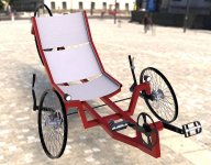
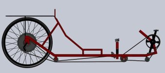
After much research, looking at a whole bunch of pictures on google, videos on youtube (Especially those of DoctorBass :wink: ) and commercially available trike manufacturer websites, I came up with this:
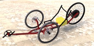
VelociRaptor Prototype 1.1.jpg


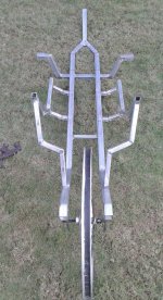
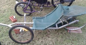
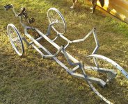
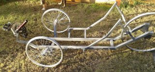
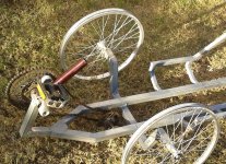
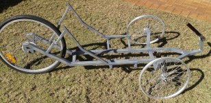
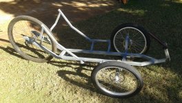
Seeing the render got me all excited, so I went to my local salvage yard and bought all the steel I needed (and then some) for $50, and got on to cutting and welding:
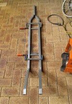
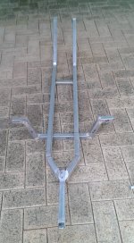
Frame P.jpg

Frame P1.jpg

View attachment 2

Frame P3.jpg

Frame Mocked.jpg


I'm hoping to get the chain drive worked out in the next week, followed by the steering, custom wheels and braking.


I look forward to any pointers anyone may have on ways I could improve the design, suggestions for motors or other components or anything else! :D


Cheers,
Rob
 
Hey Rob,
Looks great so far! You obviously have some fabrication skills. I'm building a KMX etrike so I'm interested to see what you do with this one.
I ended up going with an HS3540 and 24s3p of Lipo, but it isn't running just yet so I'll have to get back to you about how I like it. Have fun and keep us posted!
 
24s LiPo will be pretty epic. If 16s LiFePO4 gets me going nearly 60km\h, i'd be interested to see how quick you'll be going!


Update on my build:

I've started sorting out the chain drive finally. I've decided to use an "intermediate sprocket" (basically, just a rear wheel with the spokes cut off it) both as a sort of idler, and to give me a gear ratio that will actually be useable in speeds of excess of 60km\h.

Front crank mockup.jpg

Front crank mockup 2.jpg

Front crank mockup close.jpg


Also, I couldn't help myself and went ahead and bought 20 of the 10Ah Headway 38120P cells. These should give me one hell of a ride with the right controller (on the to-do list)

Headways.jpg


I've also been working on some custom 20" wheels for the front, as well as the kingpins for the steering. Pics of those will be up soon hopefully!
 
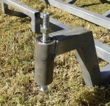
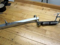
Got the kingpins welded on today and started mocking up the wheel mountings. I'm guessing this will be needing a rethink in the near future, but for now, this is the method I'll use just for getting the general idea of how it's all going to go together...


View attachment 2

Kingpins 2.jpg

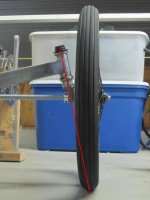
There is about 10 degrees of camber in the kingpins, but zero caster. For the time being, I'm going to keep the caster as is, until I decide that it is too twitchy at speed and \ or the brake pull is uncontrollable. I plan to be using a 'dual pull' brake lever for the front disc brakes, so in theory brake pull should be fairly minimal. Time will tell :?


Kingpin detail.jpg


That's all for now. Next up will be the idler(s) for the chain drive and getting the custom 20" wheels built. Stay tuned!
 
It's hard to tell from the pics, or have you taken scrub radius into account in the front end?

Unless you have close to zero scrub radius, brake steer may be a problem.
 
I'm pretty new to working out steering geometry. Is the scrub radius to do with the attachment point and angles for the linkage bar? If it is, I am aiming to just use perfect Ackerman angles. I have yet to fabricate the steering linkage and the 'actual' wheel mounts, so there is still a fair bit of flexibility in the design at this stage.

I'm totally open to suggestions on how to set up the steering for the best all round performance. I don't mind sacrificing turning circle for high speed stability, but at the same time, I don't want to have to do a 20 point turn to be able to get through railway crossing gates.


Thanks for your interest!
 
For zero scrub radius, you need a line along the axis of your kingpin to touch the ground under your tire.

Check out the articles on autospeed.com about building a human powered vehicle for some good info.
 
Very nice original build. Great work. Here is some photo's of the jig I used to calculate the angle for zero scrub or centre point steering
centre point steering jig.JPG
and the desired results.
Centre point.JPG
As mentioned in a previous post, the centre line of the king pins should point to the centre of the tire contact patch.

I have hit speeds of 78 km/h on a downhill run on my trike and it has been rock solid.
 
Ben,

Ah, yes, I have actually come across that in a pdf by Rickey M. Horwitz dedicated purely to the design of recumbent tricycles. Apparently I must have glanced over that section a bit briskly :oops:

Thanks for the help!


Spinner,

That is hugely helpful! Just making sure I'm looking at it right, the wheel mount tab hasn't been welded to the kingpin shaft in the first photo, and the jig is being used to position it at the correct angle? I will definitely be spending the time to do something similar I think. "If it's worth doing, it's worth doing right"

Out of curiosity, what are you doing for brakes? I can't see a brake rotor in the photo, nor any way of mounting a rim brake caliper. My biggest problem at the moment is tracking down bearings and spokes for mtb hubs with 6 bolt rotor mounts to lace into a standard 36 spoke 20" rim...


Design Update

I got bored last night and only had energy to play with Solidworks. This is the result:

VelociRaptor Prototype 1.3 small.jpg


Next weekend I guess I'll be fabbing up a jig for the wheel mounts, continuing the torturous exercise of sourcing bearings and spokes, and hopefully finalizing the chain drive :D


Thanks for everyone's interest!
 
subscribed
 
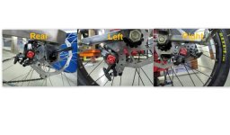
brake mounting.jpg
MagerPain said:
Just making sure I'm looking at it right, the wheel mount tab hasn't been welded to the kingpin shaft in the first photo, and the jig is being used to position it at the correct angle?

Out of curiosity, what are you doing for brakes? I can't see a brake rotor in the photo, nor any way of mounting a rim brake caliper. My biggest problem at the moment is tracking down bearings and spokes for mtb hubs with 6 bolt rotor mounts to lace into a standard 36 spoke 20" rim...


Yes, that's correct. The axle tab was not welded. I profiled the tab for a good fit and welded it to the king pin while mounted in the jig.

I mounted Avid BB7's for brakes.


You can view the entire build to completion at the link in my signature. Keep up the great work.
 
Spinner,

That is an incredible build! I was thinking something like that to mount my calipers using an assortment of weird angle iron segments and notches, but the way you've done it looks a LOT more sleek, I shall be drawing some more inspiration me thinks :)

I ordered a pair of the Avid BB7's last week, seems they are a popular choice for the weirdo's that like to build these things eh? :)

Thanks for your input, I'm sure it will save me a lot of head-scratching and subsequent headaches!

Cheers,
Rob
 
Build Update (not much to report on unfortunately):

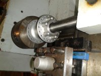
It's been a pretty slow couple weeks of progress on the e-trike because of the much needed rains coming in enormous quantities. Perfect opportunity to get behind the lathe and start fitting hubs with sealed bearings:

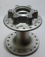
Wheel Hub.jpg

I went with Shimano 36 spoke MTB hubs with the 6-bolt brake mounting. These hubs originally came with loose ball bearings with steel races interference fit into the hubs. With a few 'high precision impulses', I was able to remove the factory races, but of course, the diameter of the bore of the hub was 25.75mm, which conveniently doesn't fit any existing bearing. So I had to skim a few hundred microns off to fit some 26x10x8 sealed ball bearings.

Centering Hub.jpg

Getting the hubs perfectly concentric in the lathe chuck was a challenge since there are no flat or perfectly round faces on the hub to squeeze the chuck down on. Using some hobbyist engineer skills, I got out the 2MT dead center (which doesn't fit in the tailstock by the way, it's just resting on the opening where there's enough of a chamfer to hold it concentric) and centered it that way. Near enough is good enough as far as I'm concerned, since the wheel can be trued to cancel out the <1mm of runout either way.

View attachment 2

This was a pretty boring job...

Being only a hobbyist using Chinese quality tools, one of the bores ended up 0.05mm oversize, which made for a very loose fit of the bearing. I used the 'internal knurling' technique I learnt from a fitter-turner friend I went to technical college with to fix this; Make a series of vaguely evenly spaced center punches around the bore face to raise the surface a little. This works great for misfits of up-to about .08mm in my experience.


View attachment 1

Not a whole heap of difference in appearance, but this will make mounting infinitely easier.


I have taken the hubs to my local bicycle store to be laced into 20" rims, hopefully they'll be done around the same time I receive my Avid BB7 brakes so I can start working out exactly how to do the mountings on the kingpins.


That's all for now!
 
Build update:

I finally got my wheels built up, and fabricated the mounts for them. I've also done a bit of a rethink for the chain drive, with my friend suggesting a really simple and elegant method for chain routing up the front.

First, the wheels:

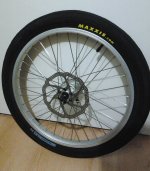
Wheel.jpg
Added some Maxxis 20 x 2.10" tires and my Avid 160mm HS1 rotors (to suit the BB7 calipers), they look pretty sweet!


All wheels mounted.jpg
Fabricated some simple mounts for the wheels, and mounted everything to get an idea of the actual ground clearance... all is well!


Chain Routing.jpg
The current model showing the chain routing method I think I'll be going with. It all works in theory, just need to put it to practise


Front Idler 1.jpg
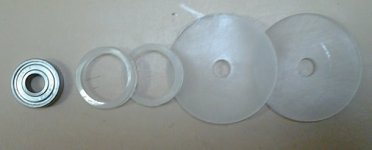
Parts of the front idler; Cut out the acrylic discs with a holesaw, then bored to fit a 22mm skate bearing in the center two discs.


View attachment 2
All of the discs are then epoxied together, trapping the bearing inside. This was the simplest method I could think of for making the idlers. Hopefully they work out reasonably.


That's all the progress for now. My aim is to have the rear idler complete by next weekend, get the chain mounted semi-permanently and make the steering arms, connecting arm and brake caliper mounts. All of this depending on weather and tiredness factor, of course.

Thanks for everyone's interest! :D
 
I've hit some snags with component dimension limitations causing severe flex and bending in certain areas, and my day job becoming more demanding on my time and energy have left me little to no time to work on coming up with a practical solution yet.

Basically, the problem lies in the fact that the wheel hubs i'm using require a 26mm outer diameter bearing, which meant that the inner diameter, and therefore the axle diameter, HAD to be 10mm as this was the only size available at the time, which is smaller than I had originally designed for. Subsequently, the axles bent on the first test ride, leaving me lost for ideas at the time. The same issue is present for the kingpins; the tubes I had used to house the bearings limited bearing choice to 10mm inner diameter, resulting in much the same problem; the entire front end developing it's own 25 degree camber :cry:

I have come up with potential solutions to this, namely, rebuilt the front wheel mount bridge thing to accept some larger diameter kingpin tubes and therefore bearings with a larger ID, and also possibly rethink the wheel mounting method, utilising a "C" bracket type thing onto which the wheel will mount, rather than the cantilevered style mounting I'm presently dealing with.

With some searching online for bearings to fit the wheels, I was also able to find some 26mm OD bearings with a 17mm ID, which would be far more ideal for the wheel axles. Only issue here is that I'd need to machine the axles from some round barstock, as to the best of my knowledge, M17 bolts are few and far between.

So yes, that is the rather disappointing reality of the state of this project at the moment.

Thanks to all those who have been following up to this point, and *hopefully* I will be able to find the time to actually attempt to apply these revisions and actually get this thing working!
 
26x17x5mm bearings won't have enough load capacity to carry the weight reliably. They're really tiny and will wear out very quickly. The cheapest way out of your stuck spot is to get some more appropriate hubs. Remember, a trike is harder on wheel bearings than a bike, because it strongly side loads its wheels.

What you want are 20mm through-axle hubs for mountain bikes. They are reasonably easy to find, they all support disc brakes, and they don't always cost much ($50 full retail at my shop, much less if you comb the web for deals). That way, you can build the axle stubs right into the frame

38708.jpg


You can pop the end spacers off to narrow the hub, if that helps. But keeping the whole 110mm width would preserve standardized axle and disc rotor spacing, and would make any 20mm through-axle hub interchangeable on the same setup.
 
Any progress?
 
Back
Top