12 Volt Electrical System
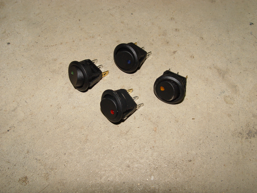
Switches for the 12 volt appliances are installed on the “dashboard” panel. The rectangular switch with the small blue lens at the top of the array is a three way switch which “shifts the gears” selecting either forward, neutral or reverse on the controllers. The four round switches are used to turn on the DC/DC converter, to turn on the 12 volt system itself, to control the daytime running lights (headlight and a tail light) and to control nighttime running lights. I separated the daytime (required by law) running lights from the nighttime running lights to conserve a bit of energy during daytime ridding. I also isolated the dc converter and the 12 volt system on separate switches so that work can be done on the 72 volt system without having power in the 12 volt wiring. This is just a personal preventative measure based on my tendency to insert metal tipped tools and my fingers where they don't belong.
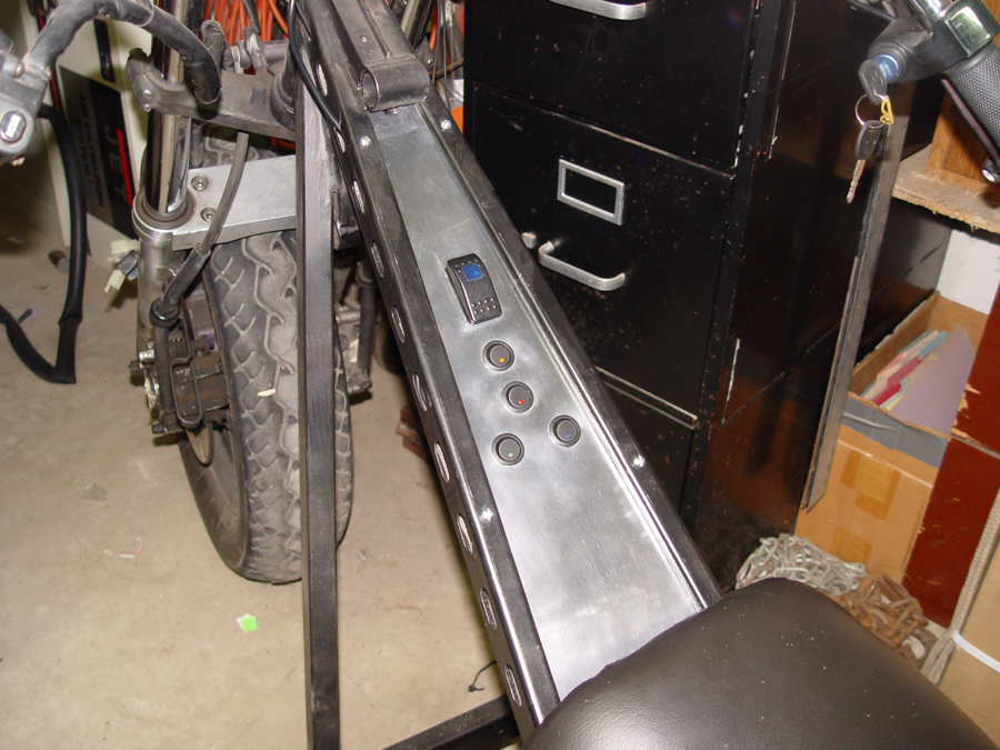
The round switches have small LED lights which indicate when the switch is in the ON position. Each switch LED is a different color to assist during night driving.
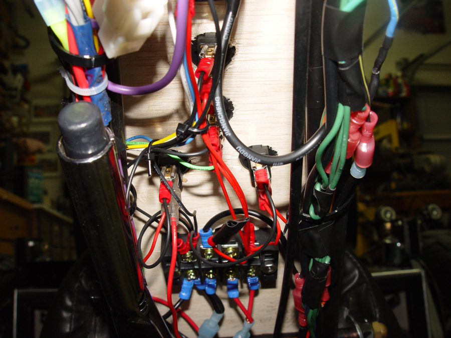
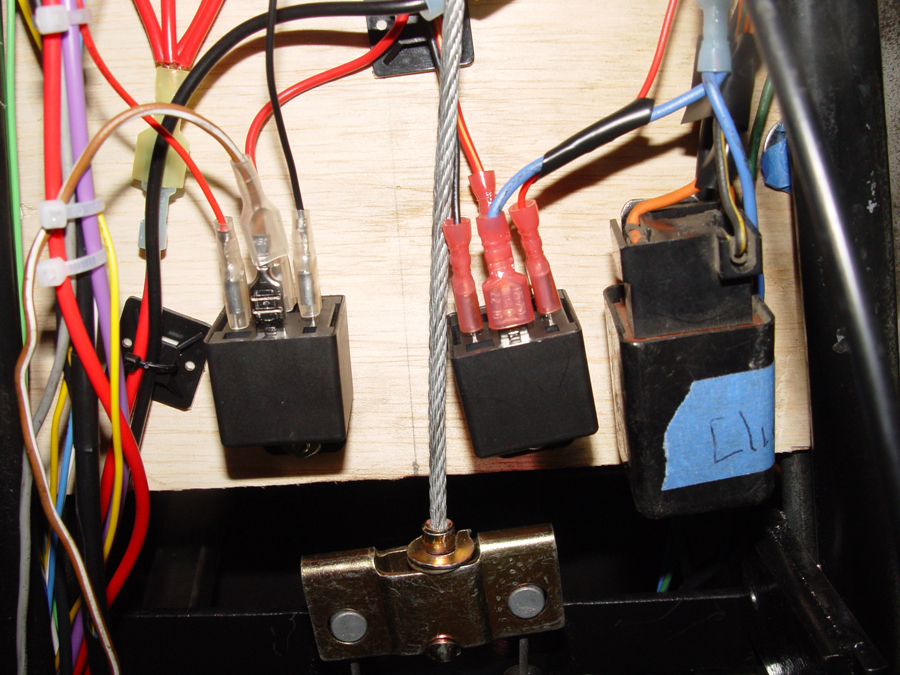
A view of the switches and wiring from under the dash. Unfortunately, neat and tidy are not among my skill set. This is actually an improvement over the initial wiring which I redid after everything functioned properly.
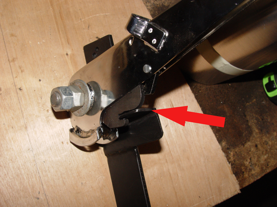
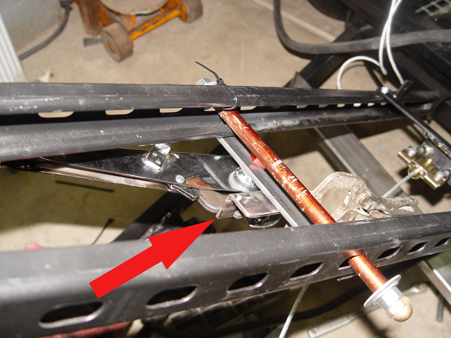
Relays for the turn signals, headlight and running lights are also located under the dash board. It would appear from this photo that the emergency brake cable might interfere with a couple wires. In reality, when the cable is pulled taut and the wiring bundled with a cable tie, everything operates without coming in contact.
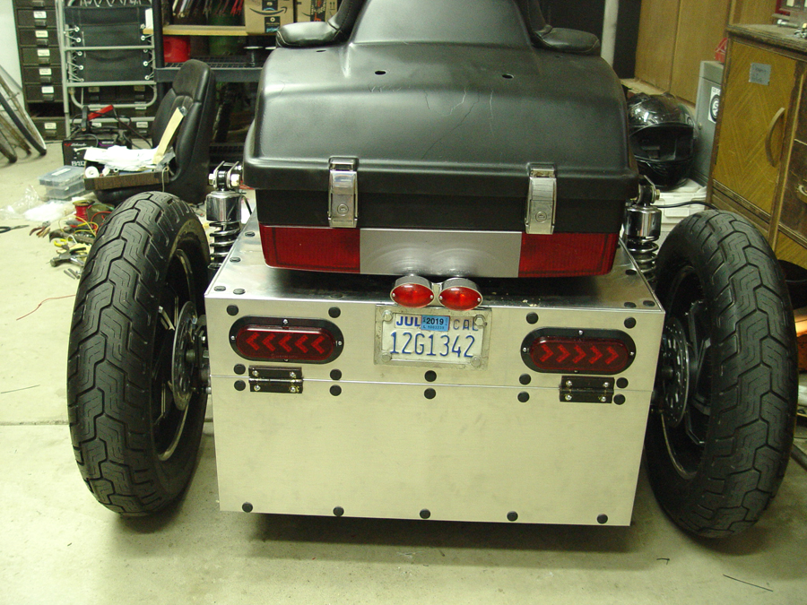
At the rear of the bike, from bottom to top, are a set of turn signals, a center array which includes the license plate light, brake lights, daytime tail lights and turn signals. Above the center array, in the lower section of the cargo case are the night time tail lights and day/night brake lights. Not shown in the photo are side markers on each side of the cargo case.
At the front of the bike is the headlight which includes hi and low beams along with internal amber turn signals. To the left and right of the headlight are external turn signals (the pointy arrow like things). These turn signals are nifty because they are on a flexible, spring-like base. If someone inadvertently hits or brushes against them, they flex and then snap right back into position.
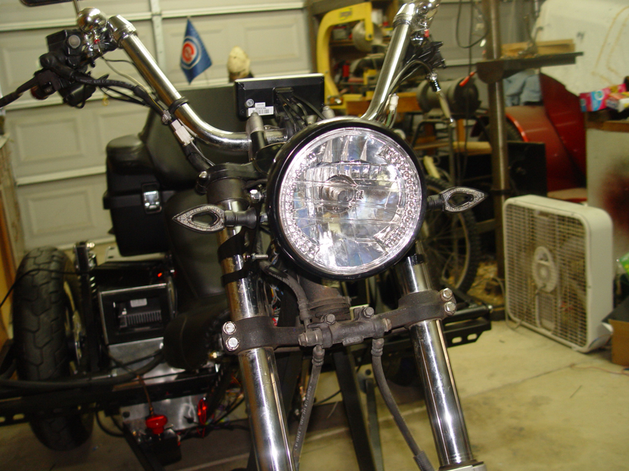
Also at the front of the bike is my poor man’s “turn signal cancellation unit”. I have turn signals on my 1,000 watt recumbent and I am forever forgetting to turn them off after making a turn. So on this bike I have mounted turn signals on the handlebars which point rearward rather than forward…right at eye level with the rider. Not only will these turn signals remind me to cancel the unit, they will actually provide a bit more notification of my turn to anyone traveling behind me, particularly at night. Also in this photo is the center mounted Cycle Analyst 3 which provides a wealth of information regarding the electrical system along with controlling many functions such as the throttle, e-brake cut off, cruise control and high temperature safety shut offs. It also provides a speedometer, odometer and keeps data for each "trip" as well as cumulative data on energy usage and regeneration.
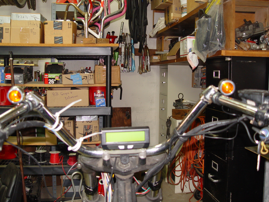
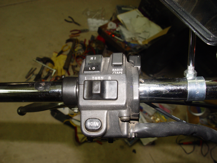
I used the Kawasaki donor bike handlebar module for control of the horn, headlight dimmer and turn signals.
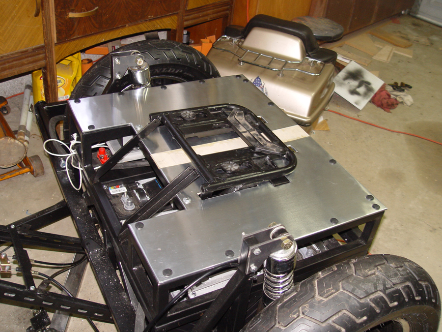
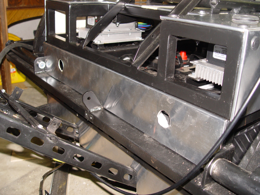
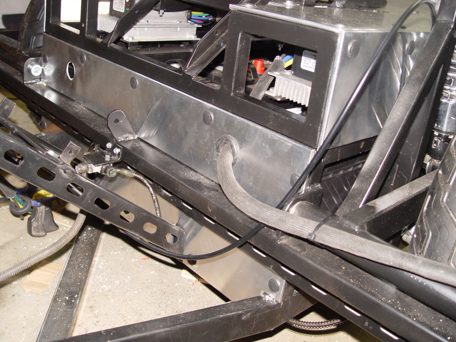
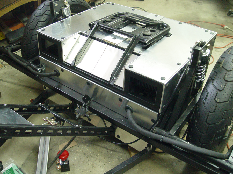
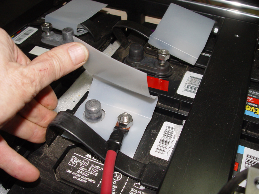
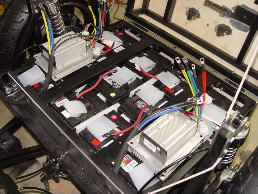
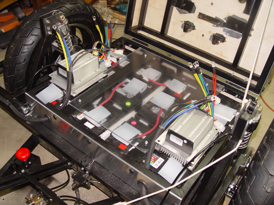
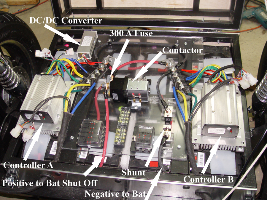
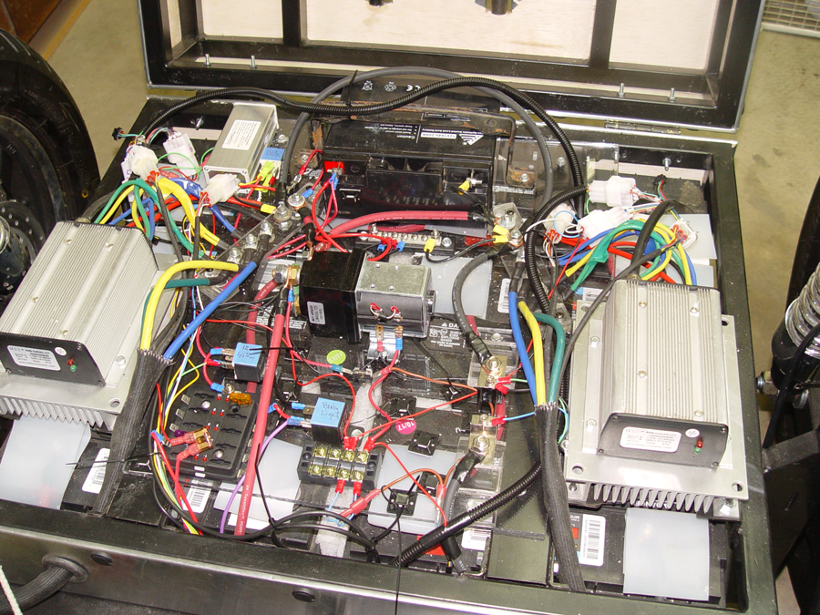
The “magic box” now containing the 12 volt system wiring along with the 72 volt wiring. Note that a 12 volt battery is installed as well as a dc/dc converter to provide power to the 12 volt system. Once the bike and electrical systems have been fully road tested, I may remove the auxiliary battery and run only off the converter.

")