
paultrafalgar
10 kW
Thanks for the update, Jason. All the best - look forward to developments in Spring.
fechter said:Wow! that's a monster.
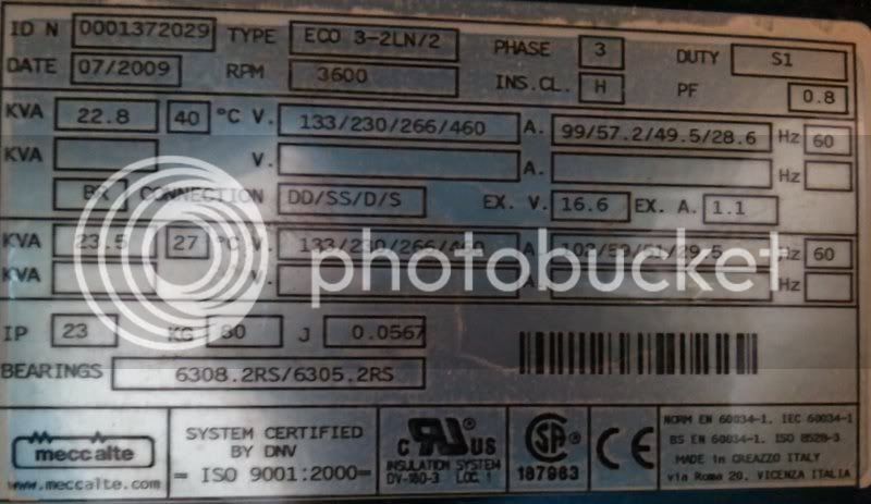
Does that have a separate field winding? I see something 16.6v at 1A on the nameplate.
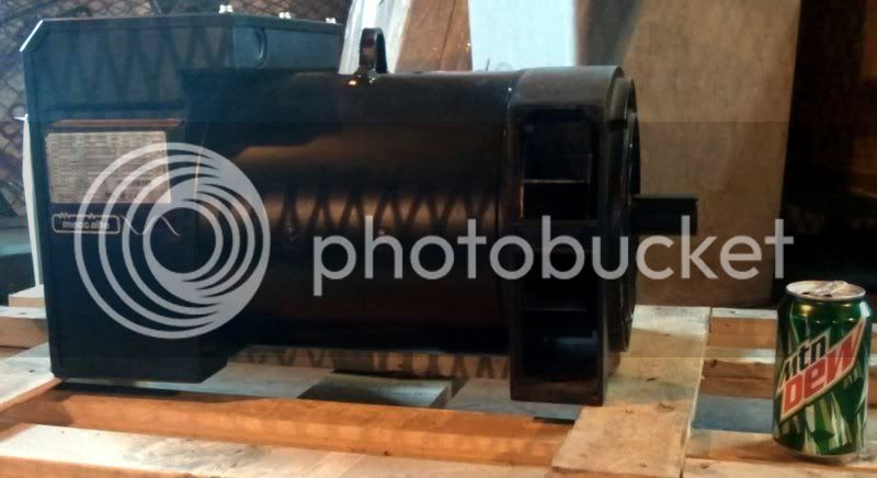
So for us folks in the slow class, this is half of the genset, right? the wee thing that'll convert the ammonia engine's motion into electricity? is this the size you've been expecting? will it fit in the trunk w/ the ammonia engine? pardon the ignorance, but why so large?JCG said:Generator (alternator) head arrived today
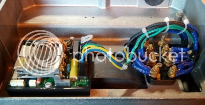
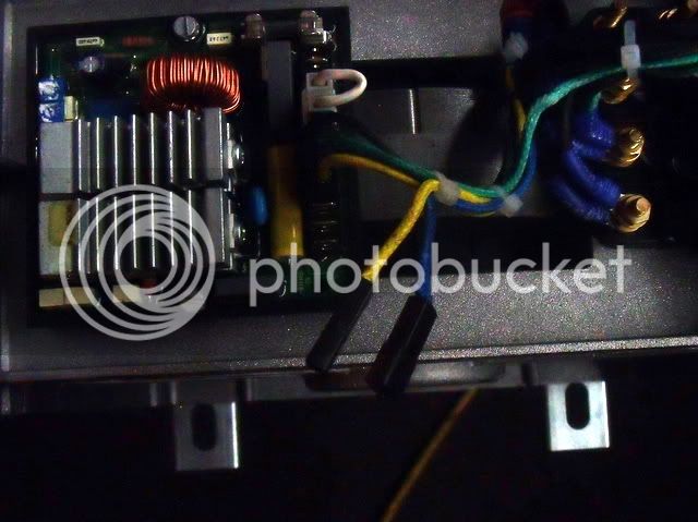
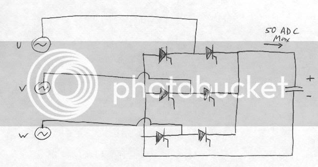
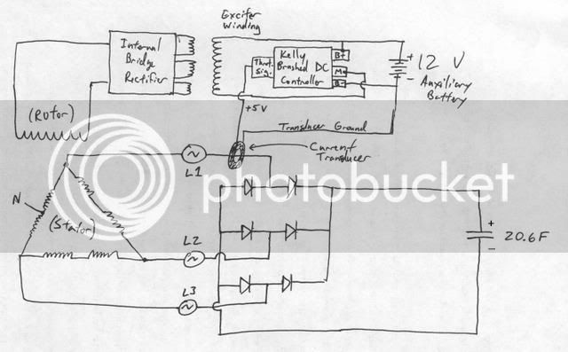
fechter said:It might be necessary to have some kind of current measurement/feedback to limit the current when the caps are starting out. I assume the regulator is a CV only. With the right current limit, the ICE should never be overloaded.
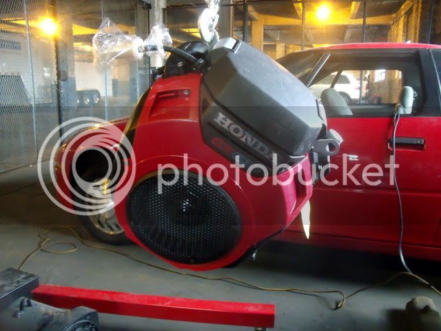
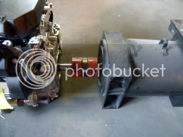
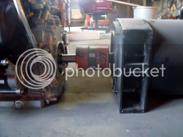


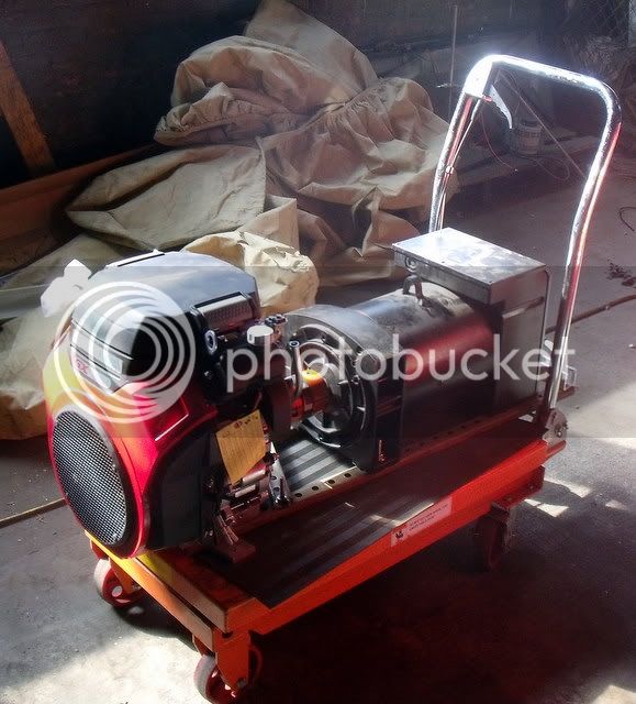
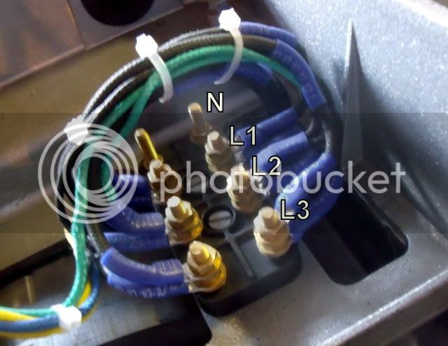
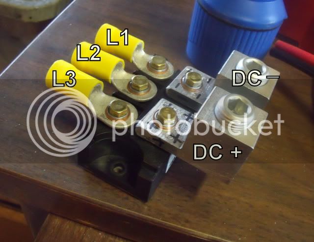

Running off ammonia, or have I missed something?JCG said:The generator head is to be coupled to a 690 cc Honda v-twin engine, which produces up to 22 hp at full speed (3600 rpm).
GCinDC said:Running off ammonia, or have I missed something?
If I wanted to bust your chops, I'd mention the noise...JCG said:Gotta bust my chops, eh Greg? :lol:
vanilla ice said:BTW we want some new pics!
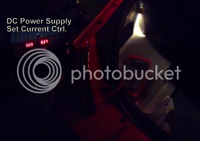
lesdit said:Are you using a switching boost supply to drain the caps most of the way, BTW ?
I ordered a bunch of supercaps to play with on my bike, and don't see any other way than to use a boost supply to effectively use the energy from the caps.
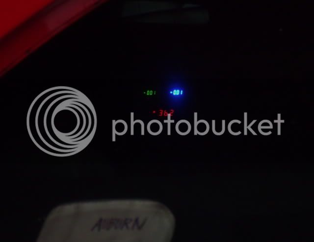
lesdit said:On your bike, I imagine that the power was really falling off as the cap voltage ramped down ? Or did the controller compensate ?
Does the EV1 also just compensate by drawing more amps from the caps as the voltage decays ?
IM willing to bet they are using Lipo batteries and the charge rate of a nano tech would be no problem!!!JCG said:Greg - that was a neat video! Very fun to watch.
Like you said, we don't know what battery chemistry they're using, so there may be a concern with charging current. Trying to dump current into some battery types will damage them, and most batteries don't have a really great charging efficiency. Caps might be a good trade to make for the batteries, but it's certainly going to limit how long their acceleration burst times will be. So the question is, would faster charging be worth limiting the total energy? Need to find out about their batteries.
Arlo1 said:IM willing to bet they are using Lipo batteries and the charge rate of a nano tech would be no problem!!!
In fact half the teams on the grid, including front runners Ferrari and Renault, have opted to use the Electric KERS system developed by Italian Auto electrical supplier Magnetti Marelli. The system itself is fairly conventional, using a single 60 Kw liquid cooled brushless direct current (BLDC) motor / generator unit, ...
.... The battery pack is mounted at the bottom of the fuel cell and in the case of Ferrari is supplied by French Li-ion battery maker Saft.
The 106-cell lithium-ion battery pack was mounted in the forward section of the vehicle’s keel to preserve the vehicle’s center of gravity and take advantage of draft air cooling.
They start the race on a fully charged pack and all they have to do is size the pack to their needs and it will take the charge no problemHillhater said:Arlo1 said:IM willing to bet they are using Lipo batteries and the charge rate of a nano tech would be no problem!!!
If they are using any of the known Nanotech lipo ( 100c discharge 10-15C charge) then charging certainly will be a problem.
The F1 KERS rules allow them to be used @ 60kW for 6.6 secs per lap . (0.11kwhrs total)
But they have very limited opportunity to regen that again in the braking periods of a lap at the 10-15C charge rate.
so, whilst the 0.11kWhrs of discharge could easily be served by a small 6kg nanotech pack, it requires a much bigger ( 5-10 times bigger) pack to be able to recharge in the available time.
More discussion here..http://endless-sphere.com/forums/viewtopic.php?f=14&t=26380
