Fardriver app understanding: screen symbols

Joined
Jan 13, 2024
Messages
51
Location
Cosmopolitan
While (still) trying to get Fardriver to do "self-learning"... :rolleyes:
In the technical app that goes with Fardriver controllers (for which seems not to exist a detailed English Manual!?),
has anyone seen and figured out what these symbols on the "Graph" screen want to communicate?
I searched google images even for the minimalist but nothing helpful coming up:

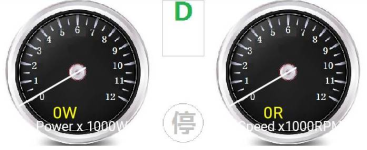
1) What means the "D"?
1711016236382.png

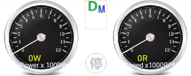
2) What means the "D M"?
1711016269189.png


3) What means the "MTPA" ? (whether with X in a circle, or with ✔ doesn't matter, that's clear then ;))
1711016424083.png


4) What means the "R"?
1711016453128.png


5) What means the what-looks-like-a-sidestand-maybe?
1711016500059.png
 
Stuff that might help (might not be what you need):

Other MTPA stuff
 
Thanks Amberwolf, by the way, love your dogs ;) St Bernards, right?

MTPA, well the point is, I don't even use this "field weakening", I am still at "learning phase", you know :cool:
"MTPA is Max Torque Per Amp, and has something to do with field weakening." doesn't fit my case. It sometimes shows the X in a circle but mostly shows checkmark, hence why I wrote 'doesn't matter, that's clear then'.

But Max Torque Per Amp, does make sense to me of course.
HereÇs the surprise, for everyone: I noticed that the app (and the controller's beeps) will at times randomly show nonsense. Yes, nonsense. :( I took screenshots each time, but it has become too much to share, not to mention, to try to solve. Exs: 7 beeps would mean:
1711100849265.png
but the motor is cold, unused :D
Or:
1711101008236.png
which, for one, at least is explained as:
1711101056463.png
only that then it doesn't disappear....
Or:
1711101104700.png
when just before it was running the motor just fine. And, "under voltage" is a joke, my app doesn't even let me change numerous parameters, incl. that one. :(

In summary: I have to conclude, the Fardriver App (Android version xx whatever) is as half-baked as most apps that I find since the turn of the millenium (when excellent programmers disappeared and got replaced by wannabe "software engineers", lol) :LOL: Titles aren't everything, I see. This, just as my personal Monday rant. :mrgreen: (which, yes, sometimes might come on a Friday)

Personally, I love to know an App inside out. But, lacking a proper complete manual from China (so far), this will take a LOT of research and testing by myself, I see.

---
The great news: I FINALLY last night got Fardriver to do "self-learning", and since then, many times :)
After the first one: OMG, was the Fardriver making my stock bike SLOW, yes, SLOW. It couldn't even get up my testing slope: 10 degrees. Which the stock controller (with full 60V rated battery) could go up at 12-13km/h (which unnerved every time, hence I got a new controller).

Meanwhile, I got the APP (oh dear) to make the Controller ✔ go with significantly more power than before :) I haven't tested the same slope yet, but will try it later.

And then, not to forget: I already have far more powerful batteries from China: After my test phase, I'll have an instant replacement from rated 60V 20Ah stock, to rated 76.8V 100Ah (I designed the dual-use option, for when I sell the stock bike). This boost should improve the uphill rides? I hope. 🙏
 
Throttle error will be set when the auto learn is not done right, or when the throttle has 0,5V lower then "trhtottle low" or 0,5V higher than "throttle high" in the app.

I had also an undervoltage alarm during regen, solution was higher values in "the stop back current" and "max back current" and lower values in the regen ratios.

To make more power you have to raise the "max line" and "max phase" current and the ratios in speed.
But be carefull , if you don´t have a temp sensor you can overheat the wires and the winding very fast.
You can set temp sensor to "cacu" and enter your rated motor power in "rated power" then the controller will calculate the winding temperature, but therefore you need to set the right motor body value.

The Fardriver controller is definitly not slow, it has either to do with the settings , the motor , the battery, or the controller is choosen to small. I have gone through a few power stages with my scooter and have measured all the values myself and can say fardriver does make the advertised currents.

If you want to disable the weakening field , you can set "weak response" to "7-none"
 
What means the "D"?
I think it might be drive.
Then maybe drive medium
R maybe reverse
Side stand circle,?not sure about but would like to know how to wire it,
 
Throttle error will be set when the auto learn is not done right, or when the throttle has 0,5V lower then "trhtottle low" or 0,5V higher than "throttle high" in the app.

I had also an undervoltage alarm during regen, solution was higher values in "the stop back current" and "max back current" and lower values in the regen ratios.

To make more power you have to raise the "max line" and "max phase" current and the ratios in speed.
But be carefull , if you don´t have a temp sensor you can overheat the wires and the winding very fast.
You can set temp sensor to "cacu" and enter your rated motor power in "rated power" then the controller will calculate the winding temperature, but therefore you need to set the right motor body value.

The Fardriver controller is definitly not slow, it has either to do with the settings , the motor , the battery, or the controller is choosen to small. I have gone through a few power stages with my scooter and have measured all the values myself and can say fardriver does make the advertised currents.

If you want to disable the weakening field , you can set "weak response" to "7-none"
Excellent info, thanks Dominik. And yes, very good reminders there, for everyone, indeed.
(I will actually add a temp sensor to the QS motor, have already wired it up.)

"field weakining" that seems to excite everyone here, I haven't looked into yet (read: not learned what it is, and if it is sensible to use on such a weak motor (rated 2k)). I am not fussed about max speed: on flat roads my bike is fast enough. Just uphills it struggled terribly.

Thx peadar too.

Earlier I wrote: "10 degrees slope. Which the stock controller (with full 60V rated battery) could go up at 12-13km/h (which unnerved every time, hence I got a new controller)."
Today, on EMPTY battery (coming back from shopping in town) the FARDRIVER still went up that same slope at 26km/h! :D
I wonder what it will be able to do when I use my new setup:
Current (stock) setup: 20Ah 60V
New (Fardriver and batteries) setup: 100Ah 77V
Today, the shopping trip was A BLAST, so much FUN!! (y):cool:

So yes, Dominik and all: The right settings make all the difference. I will continue testing them out, but can already say:
All my four days of tinkering (neighbors thought what is he doing so long on his bike there??)
were worth it: The Fardriver is a BLAST compared to the stock controller!

And no, I haven't had any jerky behavior today: Very smooth, yet rapid, accelerations, and not once "no power" - my stock controller at times left me standing on a junction, and the thing just wouldn't move: dangerous!

Here what I've been doing the past four days, may it help someone:

1711156411893.png
 
As per my earlier "In the technical app that goes with Fardriver controllers (for which seems not to exist a detailed English Manual!?",
I found the Chinese Fardriver manual, it actually is excellent (compared to most other technical app manuals), so now (for me) most app symbols are clear also. :)
I had it auto-translated (but google translation turned out to be crap), ran through it in detail to correct bad translations as best as I deemed fit, and summarized the Manual's key points for myself. - Here my summary for anyone who might be interested.

How do perform self-learning without app
---------------------------------------------------------
1. Keep the motor in the no-load state (the wheels are suspended)
2. Hold the brake or put it in neutral, and turn the accelerator fully
3. Turn on the engine and keep the throttle knob fully turned for 10 seconds
4. Now for three times: return the throttle back for 0.5 seconds, then turn it for 0.5 seconds (1), then return it back for 0.5 seconds, then turn it for 0.5 seconds (2), then return it back for 0.5 seconds, then turn it again for 0.5 seconds (3). Now return it back again.
5. The controller will beep once long and twice short, indicating that it has entered the self-learning state. At this time, follow the self-learning operation steps to complete the self-learning.
Note that turning the throttle THREE times in step 4 is to start self-learning, and turning the throttle FIVE times in step 4 is to change the direction of the motor.
Note that this method is not suitable for 485 communication controllers, because 485 communication controllers have Bluetooth and the function is blocked.
During self-learning, the controller will identify the rated speed under the current voltage, the hall sensor phasing angle (working angle), etc.

Parameters Description
---------------------------------
Speed expansion: Pushing the motor speed to a higher speed than the rated speed is called speed expansion.
Speed expansion method 1: Increase the operating voltage. The higher the voltage, the higher the motor speed.
Speed expansion method 2: Without increasing the operating voltage, increase the motor speed through field weakening.
The Nanjing remote drive controller adopts weak magnetic field speed expansion: without changing the battery voltage, it directly controls the current limiting parameters to increase the motor speed. After the speed exceeds the fixed speed, it automatically enters the field weakening state. The more the rotation speed exceeds the fixed speed, the greater the field weakening depth. Generally, the field weakening depth of hub motors can reach 50%. The field weakening depth of some hub motors can reach more than 100%. Therefore, we stipulate that the field weakening depth of surface-mounted motors should not exceed 50%. The field weakening depth of the hub motor shall not exceed 150%.

Current limiting parameter: Adjust the maximum speed by adjusting this parameter.
Let’s first talk about the conversion of 500RPM, 1000RPM,.......8500RPM, 9000RPM in the current limit. These RPMs are for the mid-mounted motor. The corresponding parameters are also those of the mid-mounted motor.
For hub motors, a conversion is required. Usually the number of pole pairs of hub motors is 16, 20, 24, 28, and 30 pairs of poles, while the mid-mounted motor usually has 4 pairs of poles.
Pole pair ratio between hub motor and mid-mounted motor: 6 pole pairs on mid-mounted motor represents 24 pole pairs on hub motor. Example for my QS motor with 23 pole pairs: 5.75 represents 23 pole pairs on hub motor.
After we obtain a hub motor pole pair value, we can set the current limiting parameters according to the speed requirements.
So, the actual speed of the 23-pole hub motor corresponding to 500RPM is 87RPM
The actual speed of the 23-pole hub motor corresponding to 1000RPM is 174RPM
The actual speed of the 23-pole hub motor corresponding to 1500RPM is 261RPM

The actual speed of the 23-pole hub motor corresponding to 2000RPM is 348RPM
The actual speed of the 23-pole hub motor corresponding to 2500RPM is 435RPM
The actual speed of the 23-pole hub motor corresponding to 3000RPM is 522RPM

The actual speed of the 23-pole hub motor corresponding to 3500RPM is 609RPM
The actual speed of the 23-pole hub motor corresponding to 4000RPM is 696RPM
The actual speed of the 23-pole hub motor corresponding to 4500RPM is 783RPM

The actual speed of the 23-pole hub motor corresponding to 5000RPM is 870RPM
The actual speed of the 23-pole hub motor corresponding to 5500RPM is 957RPM
The actual speed of the 23-pole hub motor corresponding to 6000RPM is 1044RPM

The actual speed of the 23-pole hub motor corresponding to 6500RPM is 1131RPM
The actual speed of the 23-pole hub motor corresponding to 7000RPM is 1218RPM
The actual speed of the 23-pole hub motor corresponding to 7500RPM is 1305RPM

The actual speed of the 23-pole hub motor corresponding to 8000RPM is 1392RPM
The actual speed of the 23-pole hub motor corresponding to 8500RPM is 1479RPM
The actual speed of the 23-pole hub motor corresponding to 9000RPM is 1566RPM

Field weakening limit: gradually increase the current limiting parameters. The current limit value we set should be considered based on actual needs.
For a motor with a rated speed of 850RPM and 23 pole pairs and a max field weakening depth of 50%, consider 1275RPM the maximum speed of a hub motor when using field weakening. This then corresponds to a Max 7331RPM of a mid-mounted motor. This ensures that the motor's field is weakened by 50% when idling. It will not cause the motor to shake or even burn out due to excessive field weakening.

The setting of the current limit value is to start from a safe value and gradually increase the speed. It must be ensured that the field weakening cannot be excessive. If the idling speed is unstable or even out of MOE or OVER protection, it indicates that the speed is too high and the field weakening is excessive.

Acceleration sensitivity refers to the speed of throttle response. Set this to 32 for moderate responsiveness, to 64 for swifter responsiveness.

The low throttle threshold of an electric motorcycle handlebar (which has an idle voltage of 0.8V-0.9V) will be set to 1.1V. The high throttle threshold of an electric motorcycle handlebar (which has a full throttle of 4.1-4.3V) will be set to 3.9V.
Version 742 adds a throttle self-leaming function. During self-leaming, turn the handle to the bottom and the controller will automatically identify the idle voltage and the maximum voltage of the throttle signal, and generate the throttle low and high threshold based on this voltage.

AN value (Motor body characteristic): All hub motors on the market are surface mount motors, and the AN value is generally set to 0, and not exceed 4. If the AN value is set incorrectly, the starting efficiency will be low, or even MOE/OVER protection will occur.

LM: Vehicle motor acceleration matching parameter. This value is used to adjust the smooth operation of the motor on the vehicle. The default setting is 22. The value used by most motors and complete vehicles on the market. However, there are some motor types that are poorly matched to the entire vehicle. You will feel obvious resonance vibration in the low starting speed range and the medium speed range. Adjusting the LM value will improve it. Use value 22. Only if there is acceleration jitter in the low speed section, reduce LM and start testing from 16, 14, 12, 11, 8, 5. Generally, it is better to be larger and try not to be too small. If it is too small, the current cannot be controlled. It causes MOE/OVER protection and even burn control. Therefore, the LM value at which the jitter disappears is the optimal parameter and should not be adjusted further. Some motors and vehicles are very smooth when LM=22, but changing it to a smaller value will cause jitter, so be careful. If there is no problem with LM=22, do not adjust this parameter.
Note that a MOE of 1 indicates that MOE protection is valid, while a MOE of 0 does not.

Three-speed control: high speed, medium speed and low speed. The current ratio is adjusted through 4 parameters. High gear. D is displayed on the mobile APP/computer. The power is fully on, working at the maximum line current, and maximum phase current, and maximum speed.
Medium speed: DM is displayed on the mobile APP/computer. When the power is partially turned on, the phase current affects the starting acceleration, and the line current Affects the maximum vehicle speed. it is generally set as follows: the proportion of medium-speed phase current is 75% of the maximum phase current, and the proportion of medium-speed line current is 50% of maximum line current.
Low speed: DL is displayed on the mobile APP/computer. When the power is partially turned on, the phase current affects the starting acceleration, and the line current Affects the maximum vehicle speed, it is generally set as follows: the low-speed phase current ratio is 50% of the maximum phase current, and the Iow speed line current ratio is 25% of maximum line current.

Electronic brake is controlled by two parameters: stop reflow, maximum reflow: charging current limit during reverse charging.
For the electronic braking function, when braking, the vehicle sends a braking signal to the controller, and the controller detects the braking After receiving the signal, electronic braking is performed with the current that stops the reflow, and the braking current does not exceed the maximum reflow value. Note that to use the electronic braking function, you must select electronic braking in the follow item to enable this function. and set Return current. Note that when setting parameters, the maximum reflow is generally 25% to 50% greater than the stop reflow.

Power coefficient: 0 Power coefficient, full power coefficient: parameters for calibrating power display. The controller itself can estimate the battery power, and it can be more accurate by adjusting the 0 power coefficient and the full power coeficient. Accurate battery display. When the battery is full, adjust the full power coefficient so that the displayed capacity is exactly 100%. When the battery is out of power, adjust the 0 power coefficient so that the displayed capacity and power are basically consistent. For example, when the battery is 10%, adjust the 0 battery coefficient so that the battery display is exactly 10%.

Under-voltage protection: a protective measure to extend battery life when there is a power shortage. When the battery voltage approaches the undervoltage protection point the controller reduces the power output so that the battery will not be damaged due to over-discharge.

Speedometer calibration. Hall pulse instrument: The number of Hall pulses is 1~32, 485. The instrument can calibrate the speed display through this pulse number. Analog instrument: 60V corresponds to 10000RPM

Speedometer mode: pulse/analog/isolated pulse

Cruising. There are two modes of cruising: grounded cruise and floating cruise. Generally, grounded cruise is selected, that is, the cruise line is in contact with the ground. Turn on the cruise function and drive automatically at the current speed. Pressing it again or adding accelerator or brake will exit cruise and enter Manual driving mode. Note that the maximum speed of cruising is limited by the maximum rpm of the low gear. If you press cruise when exceeding the low speed maximum speed, the system will automatically reduce the speed to the low speed maximum speed.

PID parameters: StartKI,MidKI,MaxKI / StartKP,MidKP,MaxKP. Default parameter StartKI=4,MidKI=8,MaxKI=12 / StartKP=40,MidKP=80,MaxKP=120.
The greater the motor power, the higher the voltage, and the smaller the PID. PID parameters cannot be filled in casually, otherwise it will cause incorrect work. Often even burning of the controller. The following are commonly used PID setting parameter values. There are 9 sets in total, choose one set of parameters to match the motor. The entire vehicle is modified under the guidance of professionals. Note that improper setting of PID parameters will cause the system to work abnormally, or even cause MOE/OVER/PHASE faults. If the difference is too large, it will cause burnout, so special attention should be paid to it.
-------------------------
 
You described the posibility to enter self learning mode without PC-software or Phine app.
In the app, just click in self learning turn to full throttle , wait until it turned the motor forwards and backwards, wait until motor stops, turn back the throttle and that's all.
 
You described the posibility to enter self learning mode without PC-software or Phine app.
In the app, just click in self learning turn to full throttle , wait until it turned the motor forwards and backwards, wait until motor stops, turn back the throttle and that's all.
one would think so but no go for me,have done it before so i see what you are saying
 
As per my earlier "In the technical app that goes with Fardriver controllers (for which seems not to exist a detailed English Manual!?",
I found the Chinese Fardriver manual, it actually is excellent (compared to most other technical app manuals), so now (for me) most app symbols are clear also. :)
I had it auto-translated (but google translation turned out to be crap), ran through it in detail to correct bad translations as best as I deemed fit, and summarized the Manual's key points for myself. - Here my summary for anyone who might be interested.

How do perform self-learning without app
---------------------------------------------------------
1. Keep the motor in the no-load state (the wheels are suspended)
2. Hold the brake or put it in neutral, and turn the accelerator fully
3. Turn on the engine and keep the throttle knob fully turned for 10 seconds
4. Now for three times: return the throttle back for 0.5 seconds, then turn it for 0.5 seconds (1), then return it back for 0.5 seconds, then turn it for 0.5 seconds (2), then return it back for 0.5 seconds, then turn it again for 0.5 seconds (3). Now return it back again.
5. The controller will beep once long and twice short, indicating that it has entered the self-learning state. At this time, follow the self-learning operation steps to complete the self-learning.
Note that turning the throttle THREE times in step 4 is to start self-learning, and turning the throttle FIVE times in step 4 is to change the direction of the motor.
Note that this method is not suitable for 485 communication controllers, because 485 communication controllers have Bluetooth and the function is blocked.
During self-learning, the controller will identify the rated speed under the current voltage, the hall sensor phasing angle (working angle), etc.

Parameters Description
---------------------------------
Speed expansion: Pushing the motor speed to a higher speed than the rated speed is called speed expansion.
Speed expansion method 1: Increase the operating voltage. The higher the voltage, the higher the motor speed.
Speed expansion method 2: Without increasing the operating voltage, increase the motor speed through field weakening.
The Nanjing remote drive controller adopts weak magnetic field speed expansion: without changing the battery voltage, it directly controls the current limiting parameters to increase the motor speed. After the speed exceeds the fixed speed, it automatically enters the field weakening state. The more the rotation speed exceeds the fixed speed, the greater the field weakening depth. Generally, the field weakening depth of hub motors can reach 50%. The field weakening depth of some hub motors can reach more than 100%. Therefore, we stipulate that the field weakening depth of surface-mounted motors should not exceed 50%. The field weakening depth of the hub motor shall not exceed 150%.

Current limiting parameter: Adjust the maximum speed by adjusting this parameter.
Let’s first talk about the conversion of 500RPM, 1000RPM,.......8500RPM, 9000RPM in the current limit. These RPMs are for the mid-mounted motor. The corresponding parameters are also those of the mid-mounted motor.
For hub motors, a conversion is required. Usually the number of pole pairs of hub motors is 16, 20, 24, 28, and 30 pairs of poles, while the mid-mounted motor usually has 4 pairs of poles.
Pole pair ratio between hub motor and mid-mounted motor: 6 pole pairs on mid-mounted motor represents 24 pole pairs on hub motor. Example for my QS motor with 23 pole pairs: 5.75 represents 23 pole pairs on hub motor.
After we obtain a hub motor pole pair value, we can set the current limiting parameters according to the speed requirements.
So, the actual speed of the 23-pole hub motor corresponding to 500RPM is 87RPM
The actual speed of the 23-pole hub motor corresponding to 1000RPM is 174RPM
The actual speed of the 23-pole hub motor corresponding to 1500RPM is 261RPM

The actual speed of the 23-pole hub motor corresponding to 2000RPM is 348RPM
The actual speed of the 23-pole hub motor corresponding to 2500RPM is 435RPM
The actual speed of the 23-pole hub motor corresponding to 3000RPM is 522RPM

The actual speed of the 23-pole hub motor corresponding to 3500RPM is 609RPM
The actual speed of the 23-pole hub motor corresponding to 4000RPM is 696RPM
The actual speed of the 23-pole hub motor corresponding to 4500RPM is 783RPM

The actual speed of the 23-pole hub motor corresponding to 5000RPM is 870RPM
The actual speed of the 23-pole hub motor corresponding to 5500RPM is 957RPM
The actual speed of the 23-pole hub motor corresponding to 6000RPM is 1044RPM

The actual speed of the 23-pole hub motor corresponding to 6500RPM is 1131RPM
The actual speed of the 23-pole hub motor corresponding to 7000RPM is 1218RPM
The actual speed of the 23-pole hub motor corresponding to 7500RPM is 1305RPM

The actual speed of the 23-pole hub motor corresponding to 8000RPM is 1392RPM
The actual speed of the 23-pole hub motor corresponding to 8500RPM is 1479RPM
The actual speed of the 23-pole hub motor corresponding to 9000RPM is 1566RPM

Field weakening limit: gradually increase the current limiting parameters. The current limit value we set should be considered based on actual needs.
For a motor with a rated speed of 850RPM and 23 pole pairs and a max field weakening depth of 50%, consider 1275RPM the maximum speed of a hub motor when using field weakening. This then corresponds to a Max 7331RPM of a mid-mounted motor. This ensures that the motor's field is weakened by 50% when idling. It will not cause the motor to shake or even burn out due to excessive field weakening.

The setting of the current limit value is to start from a safe value and gradually increase the speed. It must be ensured that the field weakening cannot be excessive. If the idling speed is unstable or even out of MOE or OVER protection, it indicates that the speed is too high and the field weakening is excessive.

Acceleration sensitivity refers to the speed of throttle response. Set this to 32 for moderate responsiveness, to 64 for swifter responsiveness.

The low throttle threshold of an electric motorcycle handlebar (which has an idle voltage of 0.8V-0.9V) will be set to 1.1V. The high throttle threshold of an electric motorcycle handlebar (which has a full throttle of 4.1-4.3V) will be set to 3.9V.
Version 742 adds a throttle self-leaming function. During self-leaming, turn the handle to the bottom and the controller will automatically identify the idle voltage and the maximum voltage of the throttle signal, and generate the throttle low and high threshold based on this voltage.

AN value (Motor body characteristic): All hub motors on the market are surface mount motors, and the AN value is generally set to 0, and not exceed 4. If the AN value is set incorrectly, the starting efficiency will be low, or even MOE/OVER protection will occur.

LM: Vehicle motor acceleration matching parameter. This value is used to adjust the smooth operation of the motor on the vehicle. The default setting is 22. The value used by most motors and complete vehicles on the market. However, there are some motor types that are poorly matched to the entire vehicle. You will feel obvious resonance vibration in the low starting speed range and the medium speed range. Adjusting the LM value will improve it. Use value 22. Only if there is acceleration jitter in the low speed section, reduce LM and start testing from 16, 14, 12, 11, 8, 5. Generally, it is better to be larger and try not to be too small. If it is too small, the current cannot be controlled. It causes MOE/OVER protection and even burn control. Therefore, the LM value at which the jitter disappears is the optimal parameter and should not be adjusted further. Some motors and vehicles are very smooth when LM=22, but changing it to a smaller value will cause jitter, so be careful. If there is no problem with LM=22, do not adjust this parameter.
Note that a MOE of 1 indicates that MOE protection is valid, while a MOE of 0 does not.

Three-speed control: high speed, medium speed and low speed. The current ratio is adjusted through 4 parameters. High gear. D is displayed on the mobile APP/computer. The power is fully on, working at the maximum line current, and maximum phase current, and maximum speed.
Medium speed: DM is displayed on the mobile APP/computer. When the power is partially turned on, the phase current affects the starting acceleration, and the line current Affects the maximum vehicle speed. it is generally set as follows: the proportion of medium-speed phase current is 75% of the maximum phase current, and the proportion of medium-speed line current is 50% of maximum line current.
Low speed: DL is displayed on the mobile APP/computer. When the power is partially turned on, the phase current affects the starting acceleration, and the line current Affects the maximum vehicle speed, it is generally set as follows: the low-speed phase current ratio is 50% of the maximum phase current, and the Iow speed line current ratio is 25% of maximum line current.

Electronic brake is controlled by two parameters: stop reflow, maximum reflow: charging current limit during reverse charging.
For the electronic braking function, when braking, the vehicle sends a braking signal to the controller, and the controller detects the braking After receiving the signal, electronic braking is performed with the current that stops the reflow, and the braking current does not exceed the maximum reflow value. Note that to use the electronic braking function, you must select electronic braking in the follow item to enable this function. and set Return current. Note that when setting parameters, the maximum reflow is generally 25% to 50% greater than the stop reflow.

Power coefficient: 0 Power coefficient, full power coefficient: parameters for calibrating power display. The controller itself can estimate the battery power, and it can be more accurate by adjusting the 0 power coefficient and the full power coeficient. Accurate battery display. When the battery is full, adjust the full power coefficient so that the displayed capacity is exactly 100%. When the battery is out of power, adjust the 0 power coefficient so that the displayed capacity and power are basically consistent. For example, when the battery is 10%, adjust the 0 battery coefficient so that the battery display is exactly 10%.

Under-voltage protection: a protective measure to extend battery life when there is a power shortage. When the battery voltage approaches the undervoltage protection point the controller reduces the power output so that the battery will not be damaged due to over-discharge.

Speedometer calibration. Hall pulse instrument: The number of Hall pulses is 1~32, 485. The instrument can calibrate the speed display through this pulse number. Analog instrument: 60V corresponds to 10000RPM

Speedometer mode: pulse/analog/isolated pulse

Cruising. There are two modes of cruising: grounded cruise and floating cruise. Generally, grounded cruise is selected, that is, the cruise line is in contact with the ground. Turn on the cruise function and drive automatically at the current speed. Pressing it again or adding accelerator or brake will exit cruise and enter Manual driving mode. Note that the maximum speed of cruising is limited by the maximum rpm of the low gear. If you press cruise when exceeding the low speed maximum speed, the system will automatically reduce the speed to the low speed maximum speed.

PID parameters: StartKI,MidKI,MaxKI / StartKP,MidKP,MaxKP. Default parameter StartKI=4,MidKI=8,MaxKI=12 / StartKP=40,MidKP=80,MaxKP=120.
The greater the motor power, the higher the voltage, and the smaller the PID. PID parameters cannot be filled in casually, otherwise it will cause incorrect work. Often even burning of the controller. The following are commonly used PID setting parameter values. There are 9 sets in total, choose one set of parameters to match the motor. The entire vehicle is modified under the guidance of professionals. Note that improper setting of PID parameters will cause the system to work abnormally, or even cause MOE/OVER/PHASE faults. If the difference is too large, it will cause burnout, so special attention should be paid to it.
-------------------------
thanks for all of the info still looking
 
Sorry , I thought you had described how you did it.
 
Back
Top