
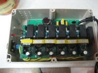
I opened up and took apart one of the 24v chargers ( 2 of these chargers came with a 48v pack )
You are using an out of date browser. It may not display this or other websites correctly.
You should upgrade or use an alternative browser.
You should upgrade or use an alternative browser.
Fatal Flaw in Chinese LiFePO4 chargers
- Thread starter oatnet
- Start date
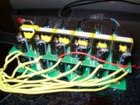
the 2 boards are bolted together with long nuts and bolts, over nylong spacers..
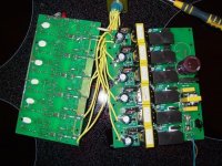
Then i had to cut the soldered leads ( 2 of them where i'm cutting )
Then i had to cut the soldered leads ( 2 of them where i'm cutting )
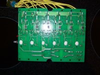
Under the top board.
bottom layer
Hopefully these pictures help explain how they work to some of you EE's, it's mostly voo-doo to me unfortunately. 
Beagle123
10 kW
Hi oatnet:
I have good news. I think you're mistaken
No, that's impossible. Batteries don't conduct electricity like wires--they will allow current to flow through them, charging them, until they become full. Then current stops. According to your diagram, the end battery would have to support all the current for all the batteries, which it would refuse to do once it is full.
Notice on your diagram that all current must flow through the positive lead of one battery. This wouldn't work at all.
Also, the voltages in your diagram don't make sense:
<img src="http://endless-sphere.com/forums/files/bad_chargers_101.jpg">
if you look at the charger furthest to the left, the positive lead is at +48v. However, the negative lead is at 0v. This is only a 3.7v charger, so it can't charge at 48v. Perhaps the common + lead serves another purpose?
I think the chargers are simply connected in series:
Each charger must use the positive lead of the charger next to it as its negative lead. So the first charger has voltage 0-4v then the next charger's voltage is 4-8v, then 8-12v etc.
Perhaps the chargers are connected to each other on their underside.
****************
To whom it may concern:
I've read this thread, and I've been working on my own battery charging solution. I reaally can't understand why more poeple aren't junking all the cheap chargers and battery balancers and charging using a power supply. I've had a big discussion with xter and fetcher about this, and I'm still convinced the best ways to charge are:
1) isolate cells and charger at 4.1v using a power supply (4v, 50A) approx $100 ebay.
2) use a bunch of those little chargers like xter and GGoodrum.
3) use safe cells like lifepo4s and charge at full voltage using a power supply. (using a 60v, 3A, ebay=$118)
If you want to see the whole discussion look here:
http://endless-sphere.com/forums/viewtopic.php?t=1833&postdays=0&postorder=asc&start=360
pages 24,25
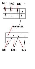
I will be using a block of andersens connectors to connect all my batteries in series like in the pic below. When I unplug the blocks, all batteries will be disconnected from each other. I will make two charging plugs that fit into both of these plugs to charge all the packs at 4.1v using a single power supply. Like this:
<a href="http://cgi.ebay.com/MASTECH-VARIABLE-REGULATED-DC-POWER-SUPPLY-0-30V-0-50A_W0QQitemZ120177187549QQihZ002QQcategoryZ32720QQssPageNameZWDVWQQrdZ1QQcmdZViewItem">30v, 50A power supply</a>
I have good news. I think you're mistaken
This single '+' lead is what disturbs me. I think that means the subcharger furthest from the '+' lead is actually charging 12 cells in serial, the next one 11 cells, and so on. I also think the cell closest to the '+' lead is getting too much current from all 12 subchargers, and thereby overcharged even when its sub-charger shuts off.
No, that's impossible. Batteries don't conduct electricity like wires--they will allow current to flow through them, charging them, until they become full. Then current stops. According to your diagram, the end battery would have to support all the current for all the batteries, which it would refuse to do once it is full.
Notice on your diagram that all current must flow through the positive lead of one battery. This wouldn't work at all.
Also, the voltages in your diagram don't make sense:
<img src="http://endless-sphere.com/forums/files/bad_chargers_101.jpg">
if you look at the charger furthest to the left, the positive lead is at +48v. However, the negative lead is at 0v. This is only a 3.7v charger, so it can't charge at 48v. Perhaps the common + lead serves another purpose?
I think the chargers are simply connected in series:
When I emulate wiring them together in a string by putting a multimeter between the '+' of one cell and '-' of the next, I see 7.4v, so they are not electrically isolated.
Each charger must use the positive lead of the charger next to it as its negative lead. So the first charger has voltage 0-4v then the next charger's voltage is 4-8v, then 8-12v etc.
Perhaps the chargers are connected to each other on their underside.
****************
To whom it may concern:
I've read this thread, and I've been working on my own battery charging solution. I reaally can't understand why more poeple aren't junking all the cheap chargers and battery balancers and charging using a power supply. I've had a big discussion with xter and fetcher about this, and I'm still convinced the best ways to charge are:
1) isolate cells and charger at 4.1v using a power supply (4v, 50A) approx $100 ebay.
2) use a bunch of those little chargers like xter and GGoodrum.
3) use safe cells like lifepo4s and charge at full voltage using a power supply. (using a 60v, 3A, ebay=$118)
If you want to see the whole discussion look here:
http://endless-sphere.com/forums/viewtopic.php?t=1833&postdays=0&postorder=asc&start=360
pages 24,25
I will be using a block of andersens connectors to connect all my batteries in series like in the pic below. When I unplug the blocks, all batteries will be disconnected from each other. I will make two charging plugs that fit into both of these plugs to charge all the packs at 4.1v using a single power supply. Like this:
<a href="http://cgi.ebay.com/MASTECH-VARIABLE-REGULATED-DC-POWER-SUPPLY-0-30V-0-50A_W0QQitemZ120177187549QQihZ002QQcategoryZ32720QQssPageNameZWDVWQQrdZ1QQcmdZViewItem">30v, 50A power supply</a>
Attachments
The only buss I see in the pic is the high voltage one on the primary sides of the transformers. Other than that, it looks the same as having a bunch of individual isolated charges in series, one for each cell(s). That would make more sense.
oatnet
1 MW
I have good news. I think you're mistaken
I am glad to hear that - I am definitely beyond my skill set, so I am working more on rumor than experience.
No, that's impossible. Batteries don't conduct electricity like wires--they will allow current to flow through them, charging them, until they become full. Then current stops.
I have never heard this before, and I have trouble accepting it. Every battery chemistry I know of has a charger designed to shut off to prevent overcharging. Heck, I have blown LiFe cells in packs, right now, that are conducting electricity - they offer no current, they accept no charge, but they conduct. Am I misunderstanding?
I know I can overcharge NiMh/NiCd, I know when the battery is fully charged I can keep slapping current through it until overheating burns off all the active material. I thought it was possible to overcharge (and explode) Lithium Cobalt... I never experienced batteries stopping conducting current when they were full, otherwise we would have no need to build cutoffs into chargers.
Notice on your diagram that all current must flow through the positive lead of one battery. This wouldn't work at all.
??? When I charge SLA/NIMH/NICD, all current flows through the positive lead of the first battery in the string. When I discharge any pack, negative ions come out through the last battery in the string. I am sorry, I don't follow you here. Am I misunderstanding?
-JD
oatnet
1 MW
quote="fechter"]The only buss I see in the pic is the high voltage one on the primary sides of the transformers. Other than that, it looks the same as having a bunch of individual isolated charges in series, one for each cell(s). That would make more sense.[/quote]
Hi Fetcher!
I am afraid my diagram is confusing, that positive bus on the yellow field is 'virtual', not something I see physically. Each subcharger has positive and negative terminals, each cell is connected at the negative terminal, and nothing is connected to the positive terminal, so I assumed a connection had to be there to complete the circuit.
Wow, like a thunderclap I just suddenly understood that these might just be the same as ypedal's wiring, that each drop might serve as the negative lead from one charger and the positive lead for the next one. I was so stuck on the +/- solder points on each charger I didn't see that is what Gaston was trying to tell me. I assumed the circuit was completed through the main power bus, because the '+' point was not terminated.
I'll do some testing tonight, wire some cells in series and to the charger, and assuming they don't short I'll measure v across each cell. If each one is pushing 3.7v then I'll know the only thing wrong here is my feeble little brain.
-JD
]
Beagle123
10 kW
Technically, I think you're right about batteries conducting electricity. You can force more current through them just by increasing voltage. But when you charge LiFePO4s, the charger raises the voltage to 3.7v and holds it there, allowing current to flow. When the battery voltage reaches 3.7v, it is equal with the charger so current stops. The chargers just have a current sensor in them to tell you when the current slows to a certain point. So as the battery charges (voltage goes up), the current gets slower and slower until the green light goes on. But the light doesn't stop the charger. Its just an indicator light to say, "the current is going very slowly right now." But the charger is still charging with current flowing into the battery. It will continue charging with the green light on until the current equalizes and stops.
This is the case on my individual li-ion chargers from batteryspace
That is true because you're charging your batteries in series. That is a fixed loop circuit so the exact current that flows into any battery flows into the others. In this situation, you can have batteries that overcharge. In a fixed loop, the current is equal at every point along the circuit, so every battery is forced to take the same amount of current. So if you charged a cell at 3.5v with a 3.7v cell using a 7.4v charger, you'd likely end up with cell voltaages of 3.6v and 3.8v because the lower voltage cell couldn't accept current without that same current going into the higher voltage cell.
Your charger works differently. It charges each cell individually. In my humble opinion this is better. However, I reserve the right to change my mind (because fetcher seems to be content with series charging).
I think you're unhappy with your charger because its slow. I speculate that they designed it using tiny little chargers so it wouldn't produce too much heat. Those little things each produce heat, and together they could easily heat up a box without a fan or good ventilation. (my guess)
This is the case on my individual li-ion chargers from batteryspace
??? When I charge SLA/NIMH/NICD, all current flows through the positive lead of the first battery in the string. When I discharge any pack, negative ions come out through the last battery in the string. I am sorry, I don't follow you here. Am I misunderstanding?
That is true because you're charging your batteries in series. That is a fixed loop circuit so the exact current that flows into any battery flows into the others. In this situation, you can have batteries that overcharge. In a fixed loop, the current is equal at every point along the circuit, so every battery is forced to take the same amount of current. So if you charged a cell at 3.5v with a 3.7v cell using a 7.4v charger, you'd likely end up with cell voltaages of 3.6v and 3.8v because the lower voltage cell couldn't accept current without that same current going into the higher voltage cell.
Your charger works differently. It charges each cell individually. In my humble opinion this is better. However, I reserve the right to change my mind (because fetcher seems to be content with series charging).
I think you're unhappy with your charger because its slow. I speculate that they designed it using tiny little chargers so it wouldn't produce too much heat. Those little things each produce heat, and together they could easily heat up a box without a fan or good ventilation. (my guess)
When charging with a constant voltage charger, when the cell voltage gets up to the charger voltage, the current will drop to near zero. If a cell is damaged, it could act like a short or open circuit.
Yes, I think they share the + connection from one cell with the - connection from the next cell. Stick the charger on and measure the voltages on each cell. As long as the voltages on all the cells stay happy, we don't really care how the charger is wired.
Yes, I think they share the + connection from one cell with the - connection from the next cell. Stick the charger on and measure the voltages on each cell. As long as the voltages on all the cells stay happy, we don't really care how the charger is wired.
Deepkimchi
1 kW
Just got my charger tonight and had to open it up to see what was falling around inside.
Just a little plastic shard that had broken off. Look like it took a side impact.
They should use a little more wrapping & padding. It even knocked the LEDs out of their sockets.
I plugged it in, fan blows and both LEDs light up red. Got to reconnect a charger wire back to the battery before I hook the charger to the battery.
Attachments
green hornet
10 mW
- Joined
- Sep 17, 2007
- Messages
- 34
They are 12Ah cells
The Leds actually came that way, ( u dont get much for 50 cents / day labor )
The Leds actually came that way, ( u dont get much for 50 cents / day labor )
I may have gotten one from the same batch - had an LED popped out and the case surface looked a bit scratched. None of which bothers me if it works properly.
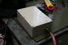
Would be nice if these chargers were small enough to carry with you, as my Lipo charger was, instead of being almost the size of a shoe box. I guess it's one of the trade-offs. It funny to me that the cooling fan started operating when I connected the charger to my pack prior to hooking up to my house outlet.
Would be nice if these chargers were small enough to carry with you, as my Lipo charger was, instead of being almost the size of a shoe box. I guess it's one of the trade-offs. It funny to me that the cooling fan started operating when I connected the charger to my pack prior to hooking up to my house outlet.
Attachments
green hornet
10 mW
- Joined
- Sep 17, 2007
- Messages
- 34
I know...
warm air will come out when charging and cool air when finished ( just in case you dont see a green lite )
all in all, for chinese, it aint bad
The taiwan stuff is coming in '08
same as A123 quality..( that people can actually buy )
warm air will come out when charging and cool air when finished ( just in case you dont see a green lite )
all in all, for chinese, it aint bad
The taiwan stuff is coming in '08
same as A123 quality..( that people can actually buy )
Deepkimchi
1 kW
Yeah - for commutes I'd buy another charger. Have one at work and one at home.
Most people go out touring and come back home, or to work and back.
I reckon cross country from hotel to hotel you'd have to lug it with you.
DK
Most people go out touring and come back home, or to work and back.
I reckon cross country from hotel to hotel you'd have to lug it with you.
DK
Deepkimchi
1 kW
Hello Fechter
If we have enough of these white box chargers go bad, can we send them to you for re-engineering?
Maybe they have the wrong FETs.... :wink:
DK
If we have enough of these white box chargers go bad, can we send them to you for re-engineering?
Maybe they have the wrong FETs.... :wink:
DK
solarbbq2003
10 kW
- Joined
- Apr 7, 2007
- Messages
- 500
Deepkimchi said:Hello Fechter
If we have enough of these white box chargers go bad, can we send them to you for re-engineering?
Maybe they have the wrong FETs.... :wink:
DK
You bet.
But you'll have to send a battery with it!
I have a yesa 8-cell LiFePO4 pack which has one of those 8-pin connectors coming off of the BMS and presumably connecting to the individual cells. I don't know how to measure individual cell voltages with it-- depending on which connectors I was using I seemed to be getting different voltage values.
As I write this I'm realizing that the pack might have a bad connection. Measuring at the charger connectors the pack voltage is almost 26.5V but measured at the power output connectors it is 22.7V. I never measured the charging connectors before using the pack but when I measured the power output connectors the voltage reading was ~26.6.
The charger, by the way, considers the pack to be charged up as indicated by the little green LED. I'm not sure how long it sat with the green LED lit but I believe it was for an hour or two... I understand having the battery plugged in while the LED is green is supposed to balance the cells somehow.
But still, I don't know how to measure the 8 individual cells correctly. Nor do I really understand why there is a difference (and how to fix it) between the output voltage and the charging connectors' voltage.
If I was correctly measuring the individual cells' voltage (using what seems to be the positive pole of the charger's connector to the positive end of the 8 pin connector, and then measuring from one pin to the next on the connector, (which gives a total of 8 voltage readings), the first reading is 2.96V from the charger connector to the 8-pin connector and the rest, from one pin to the next on the 8 pin connector, are close to 3.38.
This all leaves me just wondering what to do.
solarbbq2003
10 kW
- Joined
- Apr 7, 2007
- Messages
- 500
might be one cell is reading a bit lower, maybe that cell is not too good,
the 2.98 one? if they are full charged 3.38 seems a bit low,
b
the 2.98 one? if they are full charged 3.38 seems a bit low,
b
I (sort of) figured out how to solve the voltage discrepancy between charger contacts and discharge contacts-- I measured with the 8-pin BMS connector disconnected, and when that connector is connected the discharge contacts show the full voltage of ~26.6 again. I am not sure why undoing the BMS connector changes the voltage by that amount, but the most important thing is that the pack still works.
It seems that the method i used to measure the individual cells was flawed because when I measured by putting my voltmeter leads directly to the BMS circuitboard I found much closer to equal voltage from all cells. (each cell above 3.3V) With this and having seen how the pack performed while on the bike, I'm convinced that the cells are nearly balanced and I don't have an almost-dead cell. Simply checking voltages between different pieces of exposed metal on the pack seems a terrible way to check on the pack but I just don't know enough about how it's put together to do better. (at least I know the number of cells i'm trying to measure!) By one method i used to check what appeared to be the voltage of each cell, the readings were all about 30% too low to produce the pack's actual output voltage. I still don't know what I had measured, (There must be something in the BMS that causes a voltage drop across the connections that I measured) but clearly if the 8 cell pack produces 26V then the individual cells are not all 2.5V.
It seems that the method i used to measure the individual cells was flawed because when I measured by putting my voltmeter leads directly to the BMS circuitboard I found much closer to equal voltage from all cells. (each cell above 3.3V) With this and having seen how the pack performed while on the bike, I'm convinced that the cells are nearly balanced and I don't have an almost-dead cell. Simply checking voltages between different pieces of exposed metal on the pack seems a terrible way to check on the pack but I just don't know enough about how it's put together to do better. (at least I know the number of cells i'm trying to measure!) By one method i used to check what appeared to be the voltage of each cell, the readings were all about 30% too low to produce the pack's actual output voltage. I still don't know what I had measured, (There must be something in the BMS that causes a voltage drop across the connections that I measured) but clearly if the 8 cell pack produces 26V then the individual cells are not all 2.5V.
Similar threads
- Replies
- 4
- Views
- 989
- Replies
- 2
- Views
- 230
- Replies
- 19
- Views
- 1,004