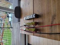
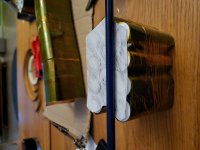
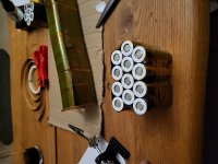
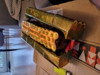
First eBike build with longevity in mind - Samsung 50G MTB Front Hub (Now rear hub)

chuyskywalker said:
Given this is your first build, I would caution that you may be over-reaching with how complicated you're making the battery build.

Thank you - I have however already made these considerations. I don't want to settle. I want to make the best that I can with what I have. I think it would be rewarding to learn as I go, and to build something that I can really feel proud of, knowing that I did what I could :) .


Grin Tech V4 Torque Arm installation:
The Grintech V4 torque arms finally arrived:
20221118_085120.jpg
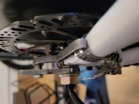
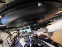
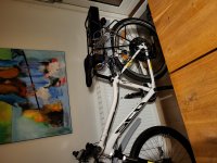
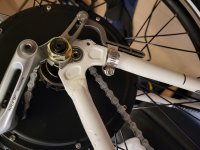
This torque arm is installed in the "wrong direction". It's installed in the wheel turn direction, opposite of the torque force direction. I just couldn't fit it in the right direction, as it would block the rear rack installation. (Bike is upside-down on the picture, in order to easily install the torque arms.)
20221118_085130.jpg
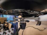
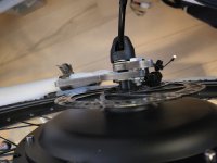
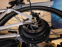
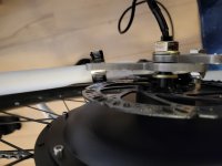
The other torque arm is installed in the correction direction, but against the chain stay (which I would also consider to be the stronger of the two stays?). Grin tech however recommends that I should install it at the seat stay - but this would also block the rear rack installation.
20221118_085138.jpg

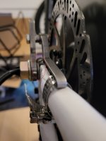
20221118_085148.jpg

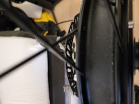
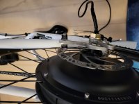
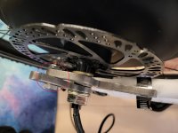
The installation of this torque arm is a little bit skewed, as you can see from the pictures above, it doesn't connection straight on the chain stay, and only connects at the very edge of the arm plate.
20221118_085229.jpg
Would it be okay to install washers here, in order to center the torque arm on the chain stay?
Anything I should be wary of, other than making sure the bolt is locking tightly?
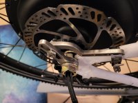
20221118_085235.jpg


Would this be okay?:
20221119_040134.jpg

20221119_041837.jpg

20221119_041926.jpg
 
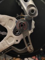
I would eliminate the torque washers outside of the dropouts. They aren't needed with the Grin torque arms in place, and just contribute to the bad alignment.
 
E-HP said:
I would eliminate the torque washers outside of the dropouts. They aren't needed with the Grin torque arms in place, and just contribute to the bad alignment.

Do you mean the washer with the tab on it?:
Tab_washer.jpg
 
Sajeel said:
This torque arm is installed in the "wrong direction". It's installed in the wheel turn direction, opposite of the torque force direction. I just couldn't fit it in the right direction, as it would block the rear rack installation. (Bike is upside-down on the picture, in order to easily install the torque arms.)
Add another hose clamp or two (you have two available empty slots) and call it good. :thumb: And that is the "correct direction" for regenerative braking, if/when you decide to use it. Overall, it is still helping secure the axle from spinning in the dropouts. :thumb:
file.php


Sajeel said:
The other torque arm is installed in the correction direction, but against the chain stay (which I would also consider to be the stronger of the two stays?). Grin tech however recommends that I should install it at the seat stay - but this would also block the rear rack installation.
Chainstay vs. seatstay is not the weak link in the equation. The weak link is the necessary tight fit of the TA on the flatted axle (you have probably noticed the Grin Tech TA fits much tighter on the axle shaft than your previous low quality knock-off TA?) and the thickness of the TA, both of which you have now taken care of. You're running 1000w motor? No need to worry about the chainstay.
Try omitting the tabbed washer (as E-HP recommends above) and see if that solves the misalignment. If necessary, you are allowed to bend that (second) piece (the extender piece that clamps to the frame) slightly to make it conform better to the frame. Added bonus: you will get more thread engagement on that axle nut. :thumb:

Looking better all the time! :D
 
E-HP said:

Thank you. It helped with the aligment of the TA - I'm only using one washer inbetween on that side now:

20221122_201002.jpg

20221122_201022.jpg


99t4 said:
Add another hose clamp or two (you have two available empty slots) and call it good. :thumb: And that is the "correct direction" for regenerative braking, if/when you decide to use it. Overall, it is still helping secure the axle from spinning in the dropouts. :thumb:

Thanks! I think I will 'hose it down' once I'm closer to the finished product in case I need to adjust things, I won't need to take off two hose clamps. Not sure I should use regenerative breaking with the KT controller. I don't want to damage anything, but it would be nice to have a passive stopping force that does not wear the brakes of the bike... But for now I'm not planning on using it - that might be subject to change tho!

99t4 said:
Chainstay vs. seatstay is not the weak link in the equation. The weak link is the necessary tight fit of the TA on the flatted axle (you have probably noticed the Grin Tech TA fits much tighter on the axle shaft than your previous low quality knock-off TA?) and the thickness of the TA, both of which you have now taken care of. You're running 1000w motor? No need to worry about the chainstay.
Try omitting the tabbed washer (as E-HP recommends above) and see if that solves the misalignment. If necessary, you are allowed to bend that (second) piece (the extender piece that clamps to the frame) slightly to make it conform better to the frame. Added bonus: you will get more thread engagement on that axle nut. :thumb:

Looking better all the time! :D

I actually didn't notice the tighter fit of the TA around the axle, but I'm sure you are right about that - It's most likely me being absentminded.

Yes, I will be running 52v @ 15A continuous ~780W.
Wouldn't bending the torque arm (not the axle plate) lower the structural integrity of the TA? I have a very small washer right now - it's really screwed in tight - would it be a problem?

More thread engagement does sound nice though.


Assembling the power connector between the controller and the rear rack housing
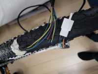
In order to fit the torque arms on both sides of the axle, I had to cut the hall sensor connector for the TA to fit through the cable:

20221121_162639.jpg

It was easily resoldered though.

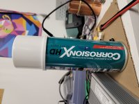
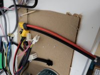
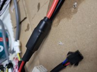
I planned to make the power cable from the controller at little longer, to give me some leeway for fitting. I connected up an XT60 male connector to the controllers XT60 female, added some CorrosionX in the connection (Highly recomended in the RC community - good for protection against water, and from rust. Dielectric up to 40.000 v.) and then I shrinktubed it:

20221121_172423.jpg

20221121_172404.jpg

20221121_173027.jpg


As you might have seen earlier, my battery housing uses an Anderson-type connector:

20221106_001613.jpg

20221106_001415.jpg

I need to connect this up to the battery housing. I don't have a crimptang for the Anderson-type plug for the connector. But I found a method online called the "Tin-pot method", where I just fill up the Anderson wire-plug with solder-tin, and then simply dip the cable down and let it cool off to make it solid:

20221121_173207.jpg

20221121_174005.jpg

20221121_174431.jpg

Looks and feels solid to me!

I also had time to do a few measurements. It seems that it might be possible for me to hide the controller under the battery housing on the rear rack. This will make the build more stealth, it will give the controller protection from the water splashes and provide decent air cooling to the controller housing - really hoping I can make this work aswell!

I'll keep you posted!
 
Sajeel said:
I actually didn't notice the tighter fit of the TA around the axle, but I'm sure you are right about that - It's most likely me being absentminded.

The tolerances of the axle flats vary from motor to motor, and even from one side of the motor to the other. On one of my torque arms, I'm able to wedge in a small piece of a razor blade in between the flat and arm. I tap it into place with a chisel and hammer, sharp edge first, and eliminates any play. On the other side, the arm is such a tight fit, I need to tap the arm into place.
 
E-HP said:
The tolerances of the axle flats vary from motor to motor, and even from one side of the motor to the other. On one of my torque arms, I'm able to wedge in a small piece of a razor blade in between the flat and arm. I tap it into place with a chisel and hammer, sharp edge first, and eliminates any play. On the other side, the arm is such a tight fit, I need to tap the arm into place.

Do you mean in between the axle nut and the TA, or in between here:

TA_Axle.jpg
 
Sajeel said:
Wouldn't bending the torque arm (not the axle plate) lower the structural integrity of the TA? I have a very small washer right now - it's really screwed in tight - would it be a problem?

More thread engagement does sound nice though.
Bending the arm such a small amount should not reduce its structural integrity to the point of becoming a problem for your intended application.

Looks like you have already removed the tabbed washer between the TA and dropout, giving you all the extra thread engagement you're going to get there.
 
99t4 said:
Bending the arm such a small amount should not reduce its structural integrity to the point of becoming a problem for your intended application.

Looks like you have already removed the tabbed washer between the TA and dropout, giving you all the extra thread engagement you're going to get there.

Yes - it's much more snug now 🙃.


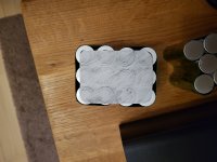
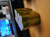
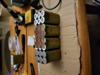
I've been working on the battery and I have gotten it all hooked up - there are some bad news tho.. I'll get to that. Here are some pictures of the process:

20221129_222050.jpg
20221129_222656.jpg
20221129_222719.jpg
20221201_185634.jpg
20221201_185658.jpg
20221201_185710.jpg
20221201_220834.jpg
20221201_185912.jpg
20221201_221414.jpg
20221202_143850.jpg
20221202_185311.jpg
20221202_185331.jpg
20221204_142605.jpg
20221204_142559.jpg
20221204_164017.jpg

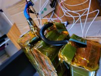
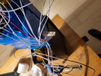
Not exactly as clean as I imagined it.. but I made it fit almost. Because of the way I made the series connections between the 3 rows, it added more length to the pack than originally planned. I'll have to 3D print an extension to the case, to make the BMS fit within the housing.

I've test connected the battery to the controller. I've had several issues.

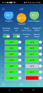
Charging the pack (with a lab power supply) the 14th parallel group (battery positive terminal) holds higher voltage than the other groups. The voltage difference from that parallel group to the others increases towards full charge - almost to 0.1v.
The pack has been resting for some days, and the difference is now at 0.03v. (4.102v for 14th group and 4.073v - 4.082v for the other groups).
Screenshot_20221219_063914_LLT.jpg

I tried to connect the battery to the controller, just to test if it would work. Nothing happens. LCD display doesn't turn on when holding the power button. Nothing happens when using the throttle.

I tested with a multimeter, and there is power through the terminals to the controller.

I have one break sensor that got broken from hitting the wall. I've just cut the head off near the break lever.

I also never connected the PAS (i didn't want to).

Other than that it's pretty standard.

20221219_070234.jpg

I've ordered a new KT controller.. and the kWeld spotwelder (i bigger and badder controller with Sinewave @ 50A peak, 25A continious). Hopefully the new controller will solve my issue.

- Sajeel
 
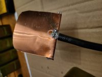
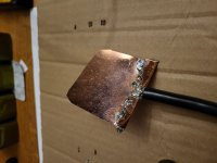
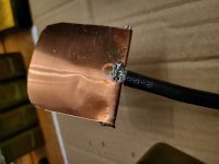
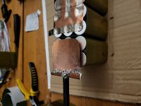
About your soldering job there:
file.php


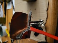
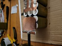
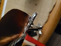
Not adequate. Doesn't really work by melting solder on top of the wire. Better is to tin the wire first, also the copper sheet mating surface. Then get the wire and copper hot enough to remelt the solder while clamped together, and add more solder until there is sufficient coverage. Will probably require a larger tip on the soldering iron (and possibly a higher wattage iron).
 
Does the brake signal wire need to be shorted in order to turn on the ebike?

My brake signal cable got damaged near the brake lever, so I just cut it off near the brake lever - I was planning to just run with a single brake wire.

Could this be the cause of the ebike not turning on?
Any experienced KT Controller users out there that ever tried to turn on their ebike, when the brake lever was pressed?

- I'll test when I'm back from Christmas holidays!

Any input is much appreciated, thank you!

- Sajeel
 
Brake levers on these (and on most) work when they are shorted together.

If the wires are cut off they shouldn't engage the brake. Even when they are engaging the brake, it doesn't prevent the controller from turning on, it simply prevents the motor from running.

If in the cutting the conductors are pinched together, they'll be shorted and engage the brake. If you haven't already, you could separate and insulate the wire ends from the controller for the ebrake you are not using, to ensure this is not the case.


However, if the controller doesn't even turn on (no 5v present), then either it is not getting power from the battery on it's battery positive and ground (negative) wires, or the "KSI" / keyswitch / ignition wire is not connected to battery positive. (also called doorlock or other wierd things depending on the horrendousness of the mistranslations).

Or if it has a display, the display buttons to turn it on has not been used (or not used correctly) or the display is defective (it has the electronics to turn the controller on) or there is a problem with the wiring or connections to the controller.
 
amberwolf said:
However, if the controller doesn't even turn on (no 5v present), then either it is not getting power from the battery on it's battery positive and ground (negative) wires, or the "KSI" / keyswitch / ignition wire is not connected to battery positive. (also called doorlock or other wierd things depending on the horrendousness of the mistranslations).

I must admit - I went home a little early because of your reply 😅. Thank you for clarifying the technical part of the brake levers.

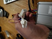
I'm almost sure it's the KSI issue that's preventing me from powering on, because I did not connect anything further to the battery positive. However I'm unsure on how to handle it / wire it up. There is another connector wired up to the display connector on the controller:

20221225_182236.jpg
20221225_183304.jpg

Would shorting that 2 pin connector with a pin provide power?
Or do I need to connect it to battery positive?
Or am I looking for another connector entirely?

Again, thank you so much!

- Sajeel
 
Sajeel said:
I'm almost sure it's the KSI issue that's preventing me from powering on, because I did not connect anything further to the battery positive. However I'm unsure on how to handle it / wire it up. There is another connector wired up to the display connector on the controller:

The KSI stuff is only for controllers without a display.

When you have a display, that has electronics in it that handle this.

Does the display turn on with it's power button?


Would shorting that 2 pin connector with a pin provide power?
Or do I need to connect it to battery positive?
Or am I looking for another connector entirely?
What does the manual (or the sales website, or manufacturer website, if any) say that connector is for, and which wire does it say is which?

If there isn't any documentation for them, then we have no way of knowing what they are for.

It's usually not worth it (because there may be no useful markings, and it is possible to damage things), but sometimes disassembling the controller and tracing where each wire goes on the board inside might tell you what voltages / signals are on each one. Measuring with a voltmeter without disassembling tells you what voltages are there, but it doesn't indicate what the signals are or what is safe to connect to what.


An educated guess, skipping NO steps below (ALL must be true up to the THEN statements):

IF

battery voltage is connected to the controller's main battery wires in the correct polarity

AND

there is no 5V on any pin of any of the controller connectors

AND

the multipin connector goes to the display

AND

the display does NOT turn on with it's power button

AND

the wire on the two-pin connector *from* the controller has battery voltage on it

AND

no other wire on the multipin connector has battery voltage on it

THEN

connecting a jumper between the two pins of the two-pin connector should connect battery voltage to the display's input.

THEN

the display should turn on via it's power button and thus also turn on the controller (placing battery voltage on a second wire of the multipin connector)

IF

the last step does not happen, then it's possible jumpering the two pins has put battery voltage on a pin of the display it is not designed for and has damaged it and/or the controller. Or a number of other possible problems.
 
amberwolf said:
Does the display turn on with it's power button?

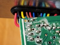
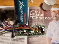
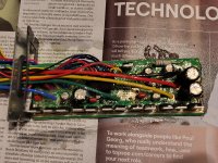
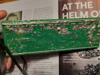
I opened up the controller to have a look and trace wires, as per your suggestion.
You were right in advising that - it also gave me an oppurtunity to do some minimal waterproofing with CorrosionX HD (very greasy stuff) and determine that I needed to short the pins:

20221225_200455.jpg

20221225_200507.jpg

20221225_201949.jpg

20221225_201955.jpg

20221225_202003.jpg

Shorting the 2 pin connector made my display turn on:

20221225_220526.jpg

I was super stoked! Unfortunately it did not last, as the throttle was unresponsive, even after fiddling with P- and C-settings.

Uggghh... when does it end 😔.

Measuring on the throttle-connector at the controller yielded 0v. Black, red, blue - GND, positive, signal.

Thanks for the logical flow-chart @amberwolf!

- Sajeel
 
I hooked up my throttle to my lab power supply and measured it - throttle works. I concluded that it was a controller issue.

I hooked everything up to the new controller I ordered and it works! :flame: :bolt: :bigthumb:
It goes 37 km/h without any resistance on the wheel. Which is a little bit short of what I had hoped for. But I'm happy that the wheels are spinning!


The only thing left is to learn CAD so that I can design and 3D print the extension and do some waterproofing as best as I can!
 
Sajeel said:
I hooked up my throttle to my lab power supply and measured it - throttle works. I concluded that it was a controller issue.

I hooked everything up to the new controller I ordered and it works! :flame: :bolt: :bigthumb:
It goes 37 km/h without any resistance on the wheel. Which is a little bit short of what I had hoped for. But I'm happy that the wheels are spinning!


The only thing left is to learn CAD so that I can design and 3D print the extension and do some waterproofing as best as I can!

Nice!
 
Sajeel said:
The only thing left is to learn CAD so that I can design and 3D print the extension and do some waterproofing as best as I can!

Congratulations!! I'm going to disagree, but there are TWO things left to do. It's a build thread. Where's the glamour shot of the fully assembled and working ebike?
 
E-HP said:
Congratulations!! I'm going to disagree, but there are TWO things left to do. It's a build thread. Where's the glamour shot of the fully assembled and working ebike?

Hehe - you are absolutely right!
Thank you for your help and contribution - it motivated me to finish this project.
It feels really nice being so close to the goal :D.
 
Back
Top