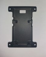
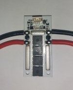
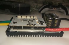
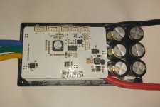
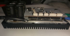
FLIPSKY new 20s 100A tiny controller (vesc based)

Hummina Shadeeba said:
I don’t think anyone here is saying u can get more torque out of low kv. It’s all the same heat to torque, but when u lower the kv u are more able to get to that max torque. No higher current esc needed.

The magnets are high temp n42sh I believe. I’m not worried about them and just trying to figure when the stator saturates.

You want to use it with this (about 110A max) ESC in particular? Than it's a perfectly valid reason I guess.
If max current at 180KV is 150A, than at half the KV it will take half the current before saturation...
 
Yeah its cheapers to go higher voltage and less current to a point like say 800volts maybe more.

Depends on the switching components and the price of them.

One simple way to look at it is the more power needed in a build the more efficency could wonder when the rpm and torque demands are not met.

So big 10kw rides are great but the potential to throw energy away as heat etc is greater than that of a system that just upto the job and no more.

Myself i try to use high a voltage as i can so on the charging side its cheaper for me to get the parts.

Decent chargery 1500w 4-24s cost me £250 a while back the bms was £130 for a 200amp jikong 24s bms thats without any cells so i see why rc batterys make sence ive used them myself for rides but ive alway ended up pushing more voltage as it was cheap for a trapiz sunwin controller that had decent power with a buttered up shunt and some lipo.

Enough power to get a 48v 1600w motor to 48mph and push the rpm from 4800 to 7800 no load but that motor died after 15 mins of flat out road riding, id discharged just under a kwh and cooked it, still spun up no broken bits just less power from demag at that point it felt like a ferrite powered motor and the heat accumulation got more and more rapid and that was 60 battery amps proberly around 120 phase amps on a motor rated for 38amp at 48v not 68v like i was feeding it.

So i creating more eddys from spinning the steel laminations faster in a switching field plus the stator itself is outputing more heat as i pushed it harder and i dont believe i saturated the motor as some push 80amps and see a increase in power as to what i was getting but its basicly a drag bike at that point 1 quick blast followed by a large cool down period.
 
BalorNG said:
You want to use it with this (about 110A max) ESC in particular? Than it's a perfectly valid reason I guess.
If max current at 180KV is 150A, than at half the KV it will take half the current before saturation...

I’m not particular about the esc. I’m trying to match the esc to the motor’s max ability.

I don’t think can assume halving current ability if half the kv. I wonder if the “max current” rating isn’t related to something other than saturation similar to how voltage ratings are put on motors. Often ratings I see on motors seem arbitrary
 
Hummina Shadeeba said:
BalorNG said:
You want to use it with this (about 110A max) ESC in particular? Than it's a perfectly valid reason I guess.
If max current at 180KV is 150A, than at half the KV it will take half the current before saturation...

I’m not particular about the esc. I’m trying to match the esc to the motor’s max ability.

I don’t think can assume halving current ability if half the kv. I wonder if the “max current” rating isn’t related to something other than saturation similar to how voltage ratings are put on motors. Often ratings I see on motors seem arbitrary

Well, I agree that that number might be somewhat arbitrary. A voltage rating however might be a safe margin for max rpm before things get out of hand (excessive vibration, magnets flying off, iron losses shooting up...) however, but it is hard to ascertain without a test to destruction :)
 
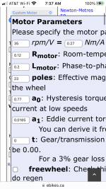
Looking on the grin motor simulator halving the kv the torque produced per amp is very close to doubling. So it is that simple.
Thanks the help on this folks. Should’ve just got on there to begin with.


But they give a max amperage with a huge kv span so unrevealing of the max amperage before saturation.
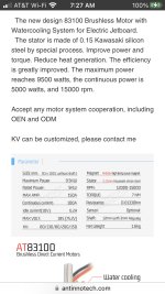
https://www.antinnotech.com/products/ant-innovation-at-83100-9-5kw-brushless-motor-with-watercooling-system-for-electric-jetboard-sensored-outrunner-bldc-motor

If assuming the stated max torque rating of the motor at 7nm is accurate, if wound to 35kv it’s about .25nm torque per amp so about 28 amps till saturation.
 

Attachments

  • 56326732-AC3F-4640-86A5-B43BD29C07EC.jpeg
    56326732-AC3F-4640-86A5-B43BD29C07EC.jpeg
    293.3 KB · Views: 1,199
  • 37007AA8-A215-41E6-9F44-EC4990DC6FEA.png
    37007AA8-A215-41E6-9F44-EC4990DC6FEA.png
    204.6 KB · Views: 1,196
Torque × rpm = hp

So hp per watt changes very little as far as the motors concerned just as we change the kv it either spins faster with less torque or vice versa.
 
Hp per watt?

The goal of spinning faster and w gearing is reduced current draw for same torque. More efficient. Trade copper losses for fewer iron losses.
 
Hp is a measurement of work done so to understand how much of a gain each wind has over the other then a way of measuring work done is needed.

Each wind will have its own merits over the other horses for courses depends how you want your rotor to saturate for example saturstion at stand still is easy to reach but as the rpm increases so does the back emf the current will reduce and the efficency climb so to saturate a moving rotor requires light loads if you dont plan on melting an end turn.

Theres lots of cooked hub motors and alike on this forum that never even reached half of saturation point let alone of stall torque but got run close to it for extended periods of time thats why rated output power is so low compared to peak power stall torque is maintainable, the motor is capable of more but its not able to sustain it.
 
The stator steel saturates not the rotor. Reads as a bunch of mixed concepts. I’m just trying to figure the one thing: at what point (current and kv) a motor will magnetically saturate.
 
Hummina Shadeeba said:
The stator steel saturates not the rotor. Reads as a bunch of mixed concepts. I’m just trying to figure the one thing: at what point (current and kv) a motor will magnetically saturate.

Auto correct motor was the intentional word i wanted please excuse as im using a phone.

Lets be clear kv is not a measurement needed to determine saturation point, stall torque is an indication of saturation the ability to no longer produce the required torque.

Since most motors give 100% of torque from 0 rpm we measure stall torque, at no point of the rpm range will it increase as back emf increases torque will reduce and efficency increase thats the point i was try to make but im not a teacher I've only been taught basics i will not be getting a call from tesla anyday soon.
 
Kv (and it’s matching kt) is a measurement that can be used figure the point of saturation and the approach I was taking.


But as u say and using stall torque as a revealer:
If I find the current at which I can no longer produce forward momentum or it’s decreasing, that’s the point at which the motor has saturated too much for the demand and possibly far beyond the point of initial saturation. It doesn’t reveal when saturation started but is caused by saturation none-the-less.. is how I see it. How can I figure when saturation starts from the stall torque?
 
Interesting but none of this has to do with FLIPSKY's controller with is the topic of this thread.

I suggest you start a new thread to continue discussing magnetic saturation...
 
I'm having a problem with the motor detection step in the FOC wizard; "sensor detection failed" error. I think I've read through most of this thread, in parts, and watched a bunch of videos, and looked on other forums, and while I see the question being posed often, the solutions are less clear.
The unit appears to be able to detect the hall sensors, since in the FOC screen, Hall Sensors tab, it's able to detect the sensors and output the table parameters without any errors, rotating the wheel in the process.
Another thing to note is that in the FOC General tab, it fails to detect/complete the motor resistance and inductance test. It errors out after the motor makes a few ticking sounds and moves very slightly.
I was trying most of the things Barncat was trying earlier in this thread, but couldn't figure out how he got it to work in the end, or at least what I attempted to do, didn't work.
Are there things to check for in order to resolve this, or is there a way to get it set up manually, without things like the resistance/inductance detection not working?

I'm trying to set this up with a Leaf direct drive hub motor.
 
Hp what controller are you using ?

I had issues with a dualtron hub, id do the resistance test but instead of no reading and time out I'd get random measurements never repeating and far apart, spining the motor would end up lossing sync and an awful sound from the motor but it was possible to manual set up the figures even then id still get red light blinking while under load and a loss of throttle till id reset so i give up that was a vesc 6.6 im sure it was faulty in some way so im hoping to have better results with this 75200 alu, i still got that hub motor im eager to test it see what occurs but id like to spin a qs138 70h with it in time.
 
20220907_133235.jpg

Had the controller today bit busy to test it out yet but the postage was 7 days china to uk even with a postal strike on so can't fault delivery time.

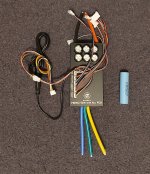
The pick shows an 18650 next to it for dimension purpose soon as i got time ill have a play with it.

Ideally i want to get it working with an accelerometer so i can launch without worrying about throttle control just hold it flat and launch.
 
As with most things from china, I usually open them up and do my own quality control inspection.

The last 75100 alu I received had a few solder whiskers floating around in the case, and while it may not immediately cause a problem, murphy's law is ever present.

Also, the soft silicone wires tend to pass over semi sharp edges in the case, I am going to heatshrink all the wires passing through the case.
 
Ianhill said:
Hp what controller are you using ?

I had issues with a dualtron hub, id do the resistance test but instead of no reading and time out I'd get random measurements never repeating and far apart, spining the motor would end up lossing sync and an awful sound from the motor but it was possible to manual set up the figures even then id still get red light blinking while under load and a loss of throttle till id reset so i give up that was a vesc 6.6 im sure it was faulty in some way so im hoping to have better results with this 75200 alu, i still got that hub motor im eager to test it see what occurs but id like to spin a qs138 70h with it in time.
This is the one I bought:
https://www.amazon.com/dp/B09J4SV7G5?psc=1&ref=ppx_yo2ov_dt_b_product_details

I'm going to try a few things today after thinking about it a while. I realized that I set the motor type to large outrunner, but noticed there's an option for an ebike hub motor. Not sure if that changes some of the parameters used for testing, but I'm hoping that makes a difference. I was also thinking of making adjustments to the current setting used for the resistance/impedance test. I think that's where it's failing, since looking at videos of the wizard setup, when it works, it seem like the order of testing is resistance test happens first, then the motor spins up, then it does the hall testing.

EDIT - well neither of those things made a difference. another observation is that the hall sensor detection will consistently work, then after doing some of the other setup stuff, going back and running it, it will consistently not detect them. I haven't figured out exactly what I'm doing before that happens, so I think I'll need to do something like recording my steps to troubleshoot that. I've checked to see that they can be detected before running the wizard, but they aren't detected there.
I guess one question is, what type of figures should I be seeing when detecting the hall sensors? Similar readings; random readings; ascending or descending? If I test twice, I mostly get the same readings, but sometimes a few change slightly.

One last thing I may try, although I don't see how it would impact things, is that on one YouTube video, the guy setting up the hall sensor connecter emphasized swapping two of the hall sensor phases. I just connected them in normal order, since I didn't see anything like that anywhere else.
 
E-HP said:
Ianhill said:
Hp what controller are you using ?

I had issues with a dualtron hub, id do the resistance test but instead of no reading and time out I'd get random measurements never repeating and far apart, spining the motor would end up lossing sync and an awful sound from the motor but it was possible to manual set up the figures even then id still get red light blinking while under load and a loss of throttle till id reset so i give up that was a vesc 6.6 im sure it was faulty in some way so im hoping to have better results with this 75200 alu, i still got that hub motor im eager to test it see what occurs but id like to spin a qs138 70h with it in time.
This is the one I bought:
https://www.amazon.com/dp/B09J4SV7G5?psc=1&ref=ppx_yo2ov_dt_b_product_details

I'm going to try a few things today after thinking about it a while. I realized that I set the motor type to large outrunner, but noticed there's an option for an ebike hub motor. Not sure if that changes some of the parameters used for testing, but I'm hoping that makes a difference. I was also thinking of making adjustments to the current setting used for the resistance/impedance test. I think that's where it's failing, since looking at videos of the wizard setup, when it works, it seem like the order of testing is resistance test happens first, then the motor spins up, then it does the hall testing.

EDIT - well neither of those things made a difference. another observation is that the hall sensor detection will consistently work, then after doing some of the other setup stuff, going back and running it, it will consistently not detect them. I haven't figured out exactly what I'm doing before that happens, so I think I'll need to do something like recording my steps to troubleshoot that. I've checked to see that they can be detected before running the wizard, but they aren't detected there.
I guess one question is, what type of figures should I be seeing when detecting the hall sensors? Similar readings; random readings; ascending or descending? If I test twice, I mostly get the same readings, but sometimes a few change slightly.

One last thing I may try, although I don't see how it would impact things, is that on one YouTube video, the guy setting up the hall sensor connecter emphasized swapping two of the hall sensor phases. I just connected them in normal order, since I didn't see anything like that anywhere else.

Hey,
Are you using original firmware? I got issue with observer on last firmware (6.0b) but needed it for the lisp integration. Seems they changed a bunch and for our hardware that may not be perfect.
Anyway detection with 5.3 firmware works all the time here (it's a standard v202).
 
Ianhill said:
20220907_133235.jpg

Had the controller today bit busy to test it out yet but the postage was 7 days china to uk even with a postal strike on so can't fault delivery time.

The pick shows an 18650 next to it for dimension purpose soon as i got time ill have a play with it.

Ideally i want to get it working with an accelerometer so i can launch without worrying about throttle control just hold it flat and launch.

Any news yet?
I'm truly considering to order a peace of this for myself. Waiting for your impressions :eek:
 
PEVSYCO said:
Ianhill said:
20220907_133235.jpg

Had the controller today bit busy to test it out yet but the postage was 7 days china to uk even with a postal strike on so can't fault delivery time.

The pick shows an 18650 next to it for dimension purpose soon as i got time ill have a play with it.

Ideally i want to get it working with an accelerometer so i can launch without worrying about throttle control just hold it flat and launch.

Any news yet?
I'm truly considering to order a peace of this for myself. Waiting for your impressions :eek:

I took a last min holiday back home next week so ill drop a post up soon as i can I'm itching to get my paws on it.
 
Scratched my itch and tested the controller few days back on the bench it spun a dualtron hub motor so thats a plus never managed that with prior iterations but ive not had time to strip it down and inspect the controller to check the design and quality.

But im hear with a warning for anyone thats got a flipsky 300a antispark this product is dangerous to the point it should be pulled from distribution.

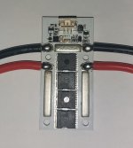
The way the board mounts in its holder means a screw passes less than a millimeter of the battery leads in the centre of them with nothing to ensure isolation its outright stupid in the event they touch the battery will melt the aluminuim case keep conducting and make a fire no doubt so if you have one pull it from your ride asap please have a look for yourselfs i dont see a fix without removing some material from the case and using only 2 of the screw its got me worried for what else gets passed the qc sticker that was stuck on it for shits and giggles.

Its got a 300a rating with 12awg wires and the pads they solder too look full (very small) id say it would tap out with heat build up after 60amp myself the water cooled version looked more robust but used heat shrink to unsure heat transfer to the water block not the best way of getting a even loaded interface between the fets and heatsink.
 
20221014_234723.jpg
20221014_234731.jpg
20221014_234814.jpg

The offending board picture with the screws shows just how close the lid sits to the solder points, the bottom screws get close to but not bang centre of the battery feed :shock:

The fet dont interface to the lid in any way its purely just a lid with no use, but to top it off the aluminuim board has been counter sunk to the same width as the screw heads so i can not drill and tap the thread and go at it frim underneath either it really is a shit show.

So close but so far, another row of fets with 8awg wires a decent mounting point for the screws and some sort of cable fixing even if its a grommet and glue but id prefer some xt 150 connector each side or alike but a grommet and glue be enough for the girls i go out with.

20221015_000119.jpg
20221015_000200.jpg
20221015_000219.jpg

And the controller itself, the solder points are acceptable theres been good flow no obvious dry spots the daughter board has been pin mounted with some pu glue the cable management of the power wires is shit but nothing some kapton tape grommets bit of case filing and pu glue cant fix the phase leads to the motor run central to the boards so ill slip a bit of fibreglass sleeve down each one and get a threeway grommet for 8awg and get that on there ill be happy enough that vibration wont be and issue on this one so a little bit of modding but a general pass from me it can do what i want its just can it last over time, hopefully ill have a ride to drop it in soon if all goes well with a kaabo wolf 10 x pro.
 
I think all Vesc based esc can do regen


This one has shown much better in many ways. https://flipsky.net/collections/electronic-products/products/flipsky-75100-with-aluminum-case-based-on-vesc-for-electric-skateboard-scooter-ebike-speed-controller
 
Back
Top