Wall of text ahead, please bear with me as i explain.
I am very much a noob with welding, and i have an old transformer stick welder with bad characteristics. Electrode sticks down rather than igniting the arc. Very difficult to start. Low-ish current welding is essentialy impossible.
But once the arc burns, its not that difficult to keep going.
So, you know HF start on TIG welders? Press a button, high voltage shoots a spark through the welding gap, the welder dumps the main welding current through the already-ionized gas and keeps the arc going.
Can it not be done on a stick welder?
Yes it's not a good idea, yes it's likely going to shock me, yes it might kill me and hurt the whole way through... Im not asking about safety here. How much safer is TIG HF anyway?
So, imagine:
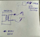
Put a cattle-prod-like circuit between stick holder and ground clamp. Great, now the current flows back and forth through the welder's transformer secondary winding.
Put a high power diode (bridge rectifier) onto the cables to block it.
--If the "HF starter" current is DC, then it would be forced right through the welding gap.
--If it's AC, then one half-wave would go through the transformer, the other half-wave is blocked and goes through the welding gap.

The diode in the picture are two paralleded 200 Amp bridge rectifiers, chinese-rated at 1600 Volt. Thus the spark-inducing voltage needs to be lower. Lets say 1 kV or so. Else it might shoot through the diode and not through the welding gap.
1 kiloVolt should produce a spark of about 1 millimeter if memory serves.
So, position electrode stick 1mm above surface, press momentary switch to get the initial spark, arc starts, welder main power takes over to keep the arc burning, continue welding as usual...
There should be very little voltage rise on the transformer secondary, since it's low resistance winding, and the spark generator circuit would be current limited (at like 40-100 mA). So no damage to the transformer...
Would this 'work', or am i missing something important?
Pls no replying 'git gud' or 'get new welder'...
I am very much a noob with welding, and i have an old transformer stick welder with bad characteristics. Electrode sticks down rather than igniting the arc. Very difficult to start. Low-ish current welding is essentialy impossible.
But once the arc burns, its not that difficult to keep going.
So, you know HF start on TIG welders? Press a button, high voltage shoots a spark through the welding gap, the welder dumps the main welding current through the already-ionized gas and keeps the arc going.
Can it not be done on a stick welder?
Yes it's not a good idea, yes it's likely going to shock me, yes it might kill me and hurt the whole way through... Im not asking about safety here. How much safer is TIG HF anyway?
So, imagine:
Put a cattle-prod-like circuit between stick holder and ground clamp. Great, now the current flows back and forth through the welder's transformer secondary winding.
Put a high power diode (bridge rectifier) onto the cables to block it.
--If the "HF starter" current is DC, then it would be forced right through the welding gap.
--If it's AC, then one half-wave would go through the transformer, the other half-wave is blocked and goes through the welding gap.

The diode in the picture are two paralleded 200 Amp bridge rectifiers, chinese-rated at 1600 Volt. Thus the spark-inducing voltage needs to be lower. Lets say 1 kV or so. Else it might shoot through the diode and not through the welding gap.
1 kiloVolt should produce a spark of about 1 millimeter if memory serves.
So, position electrode stick 1mm above surface, press momentary switch to get the initial spark, arc starts, welder main power takes over to keep the arc burning, continue welding as usual...
There should be very little voltage rise on the transformer secondary, since it's low resistance winding, and the spark generator circuit would be current limited (at like 40-100 mA). So no damage to the transformer...
Would this 'work', or am i missing something important?
Pls no replying 'git gud' or 'get new welder'...

