fechter said:
biohazardman said:
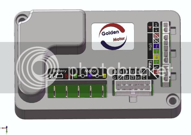
Yes, it's very plain it has the halls where you expect. Five thin wires on the right of the controller board are likely the connections from the halls.
I think those are going to the throttle, the ones on the bottom look like they go to the halls. It will be obvious once the controller is removed.
It looks fairly easy to swap the red/black battery wires on the controller. If it was mine, I'd do that for sure.
I think this should help to clarify things:
Notice the similarity with the colours and positioning of the wires:
The biggest problem with reversing the wires on the controller might become apparent if you ever needed to replace the two pin offset connectors.
If you simply chopped them off, you would need to ensure the new connector you fit joins the Black controller wire to the Red battery lead etc.
And what are the chances of remembering this at a future date?
I know it would not be very good in my case!

Here are a few things I've also spotted from this comparison:
There is nothing connected to the horn connections. (The horn was used for the alarm function and audible warning of faults etc.)
It looks like Reverse is not wired up, therefore Reverse is no longer a simple option.
The anti theft device does not appear to be be wired up, so presumably it will not automatically lock the wheel.
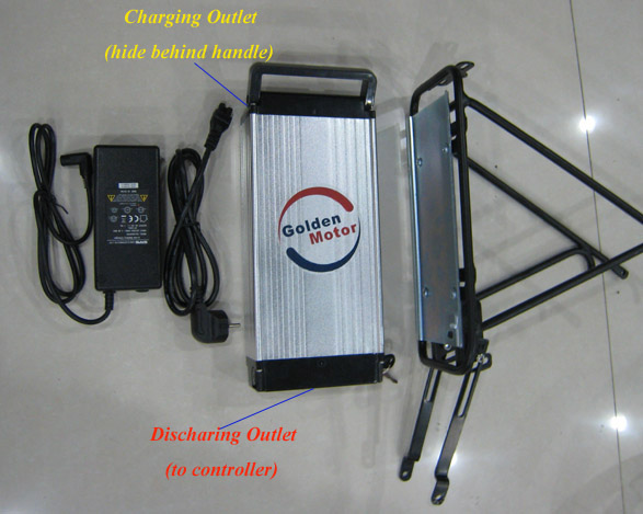
The Pedelec must be piggybacked off the throttle connection in the main harness to pick up its 0v and 5V supply, presumably done that way to reduce the number of wires passing through the axle.
I wonder if the controller board is populated and programmed to still support these missing functions, if you wanted to add the extra wiring/switches etc.
It would be nice to know.
Presumably the front wheel axle could be machined on both side to allow additional wiring to be fed through if necessary. Probably not so easy having wires exiting the freewheel side of a rear wheel.
Alan