
Hey all,
I've been lurking around this forum for a while I have been building a small electric vehicle for film making purposes. I really appreciate all the knowledge bases that is here, it's been really helpful.
My combo of a Vec500 and a Golden Motor 10kw is pretty great for general driving, but I'm having issues being able to do very slow "creeping" speeds. Sometime we will be using this vehicle for medium speed camera chases, but my clients will definitely want to those slow speeds for walk and talks. I've added a selector circuit with potentiometers to limit the throttle signal voltage to limit the throttle response but the results have been so-so.
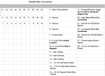
Then I started digging in the programing side and discovered the 3-Gear Function Setting. Seems like being able to switch between speed ratio percentages would be the solution but there is no real information on how you would connect a switch to the controller. In the GM diagrams, they refer to a high speed and low speed pins. Neither of them are pinned out in the connector harness and unfortunately they filled the back side with something like hot glue. Not impossible to deal with but annoying. Does anyone have any experience with wiring in those pins and how they interact with the programing? The settings in the program allows you to set a default "gear". Would I select my middle gear for default and then when I ground out the high speed pin the program switch to the high speed ratio and the same for grounding the low speed pin? Any guidance would be great.
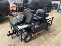
I've attached a picture of my vehicle (for fun) and a cleaned up diagram of the Vec500 Connector harness pin out that I made in excel. I was tired of squinting at the low res bad diagrams from GM. I've also found some discrepancies between their diagrams and the actuality of my harness and I've noted those in bold.
Thank so much!
I've been lurking around this forum for a while I have been building a small electric vehicle for film making purposes. I really appreciate all the knowledge bases that is here, it's been really helpful.
My combo of a Vec500 and a Golden Motor 10kw is pretty great for general driving, but I'm having issues being able to do very slow "creeping" speeds. Sometime we will be using this vehicle for medium speed camera chases, but my clients will definitely want to those slow speeds for walk and talks. I've added a selector circuit with potentiometers to limit the throttle signal voltage to limit the throttle response but the results have been so-so.
Then I started digging in the programing side and discovered the 3-Gear Function Setting. Seems like being able to switch between speed ratio percentages would be the solution but there is no real information on how you would connect a switch to the controller. In the GM diagrams, they refer to a high speed and low speed pins. Neither of them are pinned out in the connector harness and unfortunately they filled the back side with something like hot glue. Not impossible to deal with but annoying. Does anyone have any experience with wiring in those pins and how they interact with the programing? The settings in the program allows you to set a default "gear". Would I select my middle gear for default and then when I ground out the high speed pin the program switch to the high speed ratio and the same for grounding the low speed pin? Any guidance would be great.
I've attached a picture of my vehicle (for fun) and a cleaned up diagram of the Vec500 Connector harness pin out that I made in excel. I was tired of squinting at the low res bad diagrams from GM. I've also found some discrepancies between their diagrams and the actuality of my harness and I've noted those in bold.
Thank so much!
") but haing a suspension system without any bushings and only the leaf spring steel as the only moving part is something i can recommend
but haing a suspension system without any bushings and only the leaf spring steel as the only moving part is something i can recommend