Goped ESR high voltage cutoff

dnmun said:
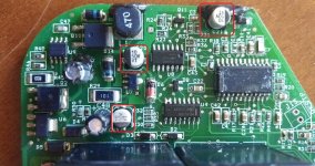
those 35V capacitors are on the 12V rail that is used to drive those relays. i think that three terminal device surface mount soldered to the surface on the right just below the B+ input is the 12V or maybe 24V regulator U6. Q9 and Q10 are the mosfets that drive the two relays and are controlled by U9. you can see the gate drive traces running from that 8 pin SOIC to the gate resistors and then to the gates of those mosfets.

i can see the programming leads to the controller too and those might allow you to reprogram the HVC.

I would hack the serial communication myself, if I had a programmer for it.. but the only way to use it is with the "goprammer" a hardware programmer that is extremely expensive, and impossible to find used.
If someone were to lend me one, I would spy on the communication and write a software equivalent.. (I am a software engineer/ systems analyst)
But without the Goprammer I cant do it. with one you can also adjust the ramp rate of acceleration and a few other cool tricks. manual for it is here: http://www.go-ped.be/Technical%20manuals/ESR%20MANUAL%202.pdf

it would also help me test that I get 100% throttle when I make my custom throttle...


When I get home tonight I plan to tear the sticker off that IC, and see if I can find any numbers on it.

btw, what makes you think its a 12v rail? the batteries are in series before being connected to the controller, so everything (other than the 5v logic) should be a 24v rail.... right?
 
i suspect the big 20 pin SOIC is an ASIIC chip. there is a big surface mount shunt resistor just to the left of the Q9 with R33 on it. i wonder what that resistor does. i just could not follow the traces enuff to find some resistor divider to produce the inverting input for the op amp that would turn off the relay if that is how the HVC is implemented as i think it must be.
 
ok, great news!
I pulled the label off.... then Using some denatured alcohol, I very carefully rubbed each chip... and I could see some numbers!

Chip 1:
Code:
AMI
CSI 27.9503
8858-005
0102LBF


Chip 2:
Code:
MC1413D  OR MCP413D (cant tell if its a 1 or a P...)
PAQ327

Chip 3:
Code:
F   (fairchild semiconductor logo)
P335F  or P33SF
MM74HC
14M


and then I promptly threw the whole thing back together and rode it back to work. (did this on my lunch break)
 
so apparently AMI was purchased by ON semiconductor in 2008.... so finding a datasheet on CSI27.9503-8858-005 is a pain in the butt..

anyone know where I can find one?
 
i think it is a programmable asiic chip so that is where the program is stored imo. looks like you are stuck with finding a brushed controller replacement. our member keywin runs a website called Ecrazyman on ebay and he sells brushed motor controllers big enuff to burn up your motor at 14S.
 
I pulled out my controller today and I noticed the cable for the gopramer connector, goped programer, has four wires and they are color coded exactly like wiring on a usb cord that I recently opened up. Is it possible to just wire up a usb to it and get some kind of info from the chip? Like accessing arduino coding or stuff like that?

IMG_2289.jpg
 
You need an interface most likely. Don't try connecting that straight to a USB port.

Did you ever figure out what the processor is?
 
There is no usb it is a different connector. I figure you are going to need some kind of program to pull/read any kind of data from whatever chip it would receive data from. The goprammer is a handheld device, I would assume it is just a simple device that some other pc program can read/write whatever data it would just the same. Here is a link of it for sale http://www.electric-scooters-galore.com/goprammer.html
 
silviasol said:
There is no usb it is a different connector. I figure you are going to need some kind of program to pull/read any kind of data from whatever chip it would receive data from. The goprammer is a handheld device, I would assume it is just a simple device that some other pc program can read/write whatever data it would just the same. Here is a link of it for sale http://www.electric-scooters-galore.com/goprammer.html

Careful with people that say they have them for sale new.... They havent made any in years, and PMW has been out of stock for a long time. If you can find one used that would work, but there are no new ones.

The Goprammer uses TTL level serial commutation. its not hard to emulate with a tiny bit of work, and a PC.. but even if you know how to talk, you still dont know what to say. Thats one of the reasons I want a Goprammer so bad.. I could wire in a pc to "peek" at whats going on. Copy the commands from the goprammer, and reverse engineer it down to a simple circuit and some software.
 
The hardware is not that hard to come up with. If you could get a copy of the software then you could be in business.

There has to be a resistor somewhere that divides the pack voltage for the circuit to sense. Adding resistance in series would solve the problem.
 
It would be so much nicer to be able to adjust it thru the programmer port. What do you think should I solder a usb to it and see what happens hooked up to my pc? Any kind of program I could start with to try to get some kind of data just to see?

I do have both the lithium ion and sla controllers so we would see some differences in the coding of each which may give us some kind of idea which is which.
 
I am going to be making some improvements to the ESR controller. (CS1115 unit built by Controls Solutions LLC)

This seems like the best thread to add to. Stand by

FYI the pics in this thread are of the older revision, likely a Gen2 unit. Not huge differences but thought to call it out.

Small teaser shot of 35v caps swapped to 50v on the Gen3 unit
small.jpg

I have a rough schematic that I created from tracing the lines and such. Here is some basic info I've gathered from reading the chips under a scope. Also depoped a few things and hooked up to component tester.

Not sure if anyone else plays around with their controller. Here are some of the parts on the board:

PIC16F88, MM74HC14 (inverter for throttle and charging), MC1413D (drives current for relay/throttle), Power pieces (MJD127/122, IFR9024, MC34063A, MMBZ5221B) and IFR3205 main fett motor drivers.
Unknown AMI micro-controller that seems to be the brains. Anyone know the datasheet for this? (ON Semi bought AMI)

Transistors on the board are generic PNP or NPN 600mA SOT23. Most diodes are 600mV forward voltage, saturation .42 micro Amp
Relays are VF7-11H12 24VDC
 
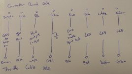
Throttle wiring to controller board:
throttle.jpg

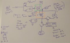
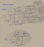
Basic motor control function. Relays (24v 70a max) act as contractors that bridge batt + voltage before PWM generated. There are four fetts in parallel that each have a Gate from PWM output of AMI controller to sink GND signal. (Just one shown in green) There are matching set of 4x fetts that appear overvoltage or regen management (marked in orange) Power filtering caps shown in bottom left of the basic motor schematic area.
control.jpg

Yes and I already know brush controllers/motors are crap and I should not be wasting my time. But I am in an apartment where I do not have the ability to fab up the needed mechanicals to swap over everything.
 
Caps can be swapped out for 50V rated instead of the 35V. Most of the transisitors are 40V or higher rated. Did anyone figure out what needed to be swapped on the board to accept the higher voltage?

Seems like 9S LiFePO4 would not be a bad candidate. (3.3v x 9 = 29.7 nominal)

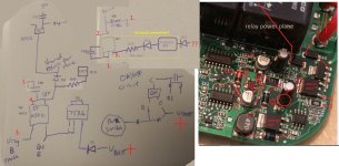
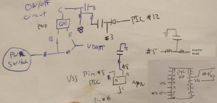
Tried to sketch the on/off & voltage portion. On/off leads to #3 (BTW updated in posts below) to make Vreg B enable which creates 18V around the board. D8 is a voltage regulator Zerner diode (MMBZ52xxBLT1G series) with output at 5V going to the AMI uC (perhaps to be sure it comes up first). Not sure where the ?? portion comes in but appears it feeds a step down converter to create 5V

(BTW I edited the picture to create combined earlier post + my basic schematic, best to right click and "view image" to zoom)
power.jpg

My #4 in the sketch also goes into the darlington transistor array but seems to just end with a capacitor? Not sure what that would accomplish.

AMI control output:
AMI.jpg
 
IMHO...why bother?

This controller is old and you can buy brand new brushed EV grade controllers that are a lot better and more powerful for less than $30.

Just my opinion, but I'd toss this is the scrap electronics bin and buy something new.
 
ElectricGod said:
IMHO...why bother?

This controller is old and you can buy brand new brushed EV grade controllers that are a lot better and more powerful for less than $30.

Just my opinion, but I'd toss this is the scrap electronics bin and buy something new.
Yeah I feel ya. But then we would of scrapped all the LPs and 8bit video game systems.
 
MrDude_1 said:
dnmun said:
i thought this had been solved already. silvia decided to buy another controller but if someone with this controller wants to pursue finding the voltage divider we can try to figure it out.
If it was ever solved, the answer has been lost with the database of goped nation.

I am all for perusing it... but I worry about blowing my controller as no one has any in stock, and I commute to work with the goped. Right now I couldnt buy a new one if I wanted to.

Low voltage cut-off is configurable with the Go Prammer. High voltage cut-off is not a field you can adjust.

Sorry 5 years too late but I think the two resistors and cap to create the voltage divider was over by Q11. I forget that I updated that unknown part of the schematic. The updated connections are below where the #8 is part of voltage sense by the PIC controller that then influences #3.
output_PNP_2.jpg

I am guessing that the HVC and LVC are related to #3 & #5 that go into the darlington transistor array to control the Vregs.

Perhaps PIC Pin6 is configured as an input with the weak pull-up enabled. It will then drop when #8 activates the NPN.
So change the resistor value that feeds #8 to change the over volt cut-off and enable 9S LiFePO4 usage?
 
aztecsurf said:
Still riding!!! Brushless, VESC setup, super reliable! Have three going now and looking to upgrade the motor later on one as a test for more power..

Which VESC controller are you running?
 
ESR_RSE said:
Anyone else still riding the Go Ped ESRs?
I am!
I have three ESRs and a GoQuad kart:

  • ESR750H PPV with Torkinator: revived the 4 LiPo packs a couple of months ago and been truly enjoying it since
  • ESR750 #1 (good motor, mostly complete): just ordered replacement SLAs (I know SLAs suck, but I found a good deal on a set of new deep-cycle SLAs that I hope will work nicely and I figured I'd get them to see if I can get the GoPed running this weekend...)
  • ESR750 #2 (bad motor, incomplete/missing parts): will try to convert this one to a custom, brushless setup
  • GoQuad (stock, 2-stroke): planning on converting this one to two motor, RWD brushless system

I am just now getting started in the PEV world out of curiosity/hobby. I am not very good with reverse-engineering boards (this is when I regret not going for an EE degree), but I can build and solder anything. Would love to work with you guys on these projects and share notes! :thumb:
 
Nice to see more folks. If any of your controllers are not working Rusty at GoPed.com is offering a repair service now.
 
The startling discovery of the Goped ESR controller in 2022. I'll be despised by Go-ped for this:


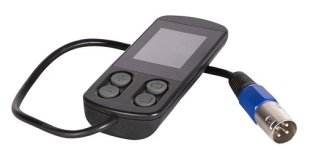
The ESR750s electronics are from a mobility scooter made in the USA. This results in it being so expensive ($265). The legendary and notorious "Go-Prammer," which no one seems to possess or be aware of, is nothing but a mere "mobility scooter programmer" with a Goped sticker, LOL! Due to legal requirements, the controller settings for the ESR750 have been greatly reduced to +750w (20/40A). I believe a compatible 4-pin mobility scooter programmer will enable you to unlock up to 150A (common for wheelchairs).

Go-Ped made it clear that they created everything in-house, but when I inquired about the ESR750s controller and programmer, they were completely clueless (me, no English). The only reason they continued using these mobility scooter parts was to keep everything "made in the USA". I genuinely doubt that they ever sold the Go-Prammer, but instead put it up on their website to give the impression that the controller is cutting-edge (programmable) - it's actually an early to mid 90's technology. They want $265 for a +3000w (150a) wheelchair controller that is restricted to only 40a (750w), which typically cost $15-$50 on ebay. To make matters worse, they will NEVER sell you the Go-Prammer or provide you with any information about it.


I'm hoping that by using this knowledge, someone may be able to devise a method for fine-tuning the ESRs controller using a 4-pin mobility scooter / wheelchair programmer.
4-pin Programmer for mobility scooters.jpg
 
2Phast2Delirious said:
I genuinely doubt that they ever sold the Go-Prammer, but instead put it up on their website to give the impression that the controller is cutting-edge (programmable) - it's actually an early to mid 90's technology. They want $265 for a +3000w (150a) wheelchair controller that is restricted to only 40a (750w), which typically cost $15-$50 on ebay. To make matters worse, they will NEVER sell you the Go-Prammer or provide you with any information about it.
if it helps
https://www.billetboard.com/forum/scooters-electric/electric-scooter-how-to-s-diy-section/13052-?p=254358#post254358
ajetsrgn1
11-04-2018, 01:36 AM
I have a goprammer.
There are 4 parameters u can set 0-100%
econo speed
econo acceleration
turbo speed
turbo acceleration.
I bought a new esr and all parameters were set at 100%.
I live in los angeles and will help if possible.
I would never let my prammer leave my sight.
 
Thank you for the info! You can configure those parameters exactly the same way on a programmer for a mobility scooter. Is the software inside the controller, and the "programmer" is simply an LCD screen with buttons?
 
Back
Top