hacking into chinese bms board to get overcharge signal

JackB

10 W
Joined
Apr 28, 2013
Messages
86
Location
Sacramento, CA
I am trying to finish up an ebike setup and the last thing that is driving me crazy is to setup a led to indicate the battery is full while the charge is hooked up. My charger is just a dumb power supply and have lifepo4 cells.
I am using one of those cheap chinese bms boards that has mosfets that get turned off when a cell reaches max voltage (3.6v on this board).

I want to hack into this board to get an input voltage to an arduino, so when the mosfets get turned off I turn on the full led,
and if really ambitous turn off a relay to turn off the actual power supply. Anyone try this?

I tried to just tap into the mosfet gate pin and put in a voltage divider, but this board is using like 1M ohm resistors,
so the microprocessor chip has trouble reading the input. The bms board is designed to consume almost no power while its hooked up to the cells, otherwise it would drain the battery just sitting there. But I think the mosfet gate doesn't need that big a resistance as the gate just charges and shouldn't consume any current after that.

I know there are other ways to do all of this, but I need to get this thing finished like a week ago, so there is no time to order any parts and wait days to get them as all the local suppliers are long gone, so its online ordering only these days.
I do have a lot of surplus electronic parts pile, as was going to build a current sensor from an old rc battery charger board I have plenty of, but more hassle and parts, if I can just hack into the bms board seems so easy and simple, but so far, not the case.

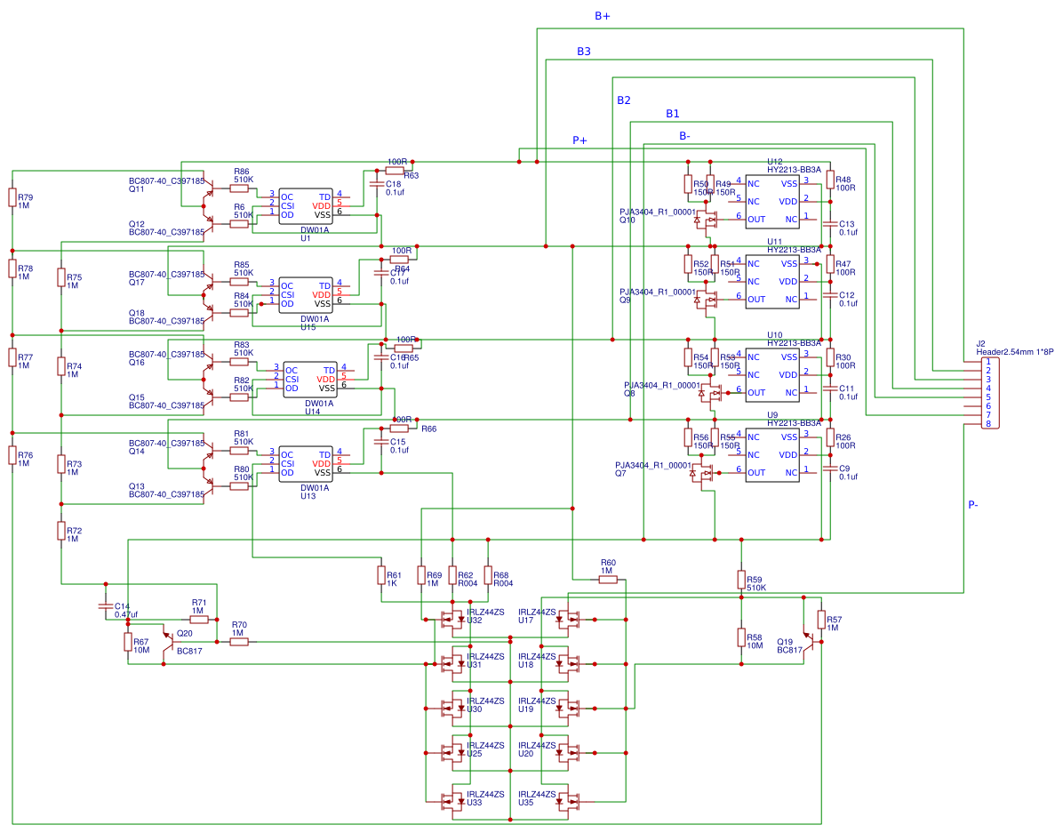
hey so I have attached a schematic of one of these bms boards. Not sure its exactly the one I have but they are all very similiar.
You can see it has a chip for each cell that turns on a fet to get voltage to another fet that grounds the gate pin on the power fets that connect the input/output (P- to the pack B-).

71a2fdf3766c4cecba7020c4973b4316.png
 
FWIW, the main FETs of the BMS will turn off and back on several to many times during charging and balancing; until they turn off and stay off because all cells are now in balance and full it isn't done charging.

If at some point you want to order something, you can buy boards that read the pack voltage and shut off at that point, or ones that detect current has dropped below a setpoint you choose and disconnect the power supply from the battery. The latter type basically turns your power supply into a charger, as that is how chargers generally terminate charge.

You could emulate this with your Arduino, by measuring the voltage across the BMS shunt (if it has one) and having the Arduino turn off a relay between the PSU and the battery when the voltage across the shunt drops below the value that matches your chosen termination current limit.

If your BMS doesn't have a shunt, you can get or make one, it just has to be a conductor with sufficient resistance (usually one to several milliohm) to develop a voltage across it that your Arduino can read (or that you can amplify with an op-amp), and that doesn't change resistance very much within the temperature range the equipment is used in. (so the voltage across it at any specific current doesnt' vary much because of that). You will need to calibrate the shunt (find out it's exact resistance), and since you probably don't have an ohmmeter capable fo reading such a low resistance, your best bet is to use an exact current thru it (high enough to measure accurately with your ammeter or multimeter) and measure the voltage across it, and then use ohm's law to calculate the resistance, that you can then use in your software to calculate any current thru it based on the voltage across it.


If you only want to trigger on just one cell's "full" signal, you could tap off the appropriate signal pin (OC or OD on the schematic you've posted) on the *most negative* cell's detection chip, and when the signal changes, have your software do what it needs to do. One of those signals will probably be to turn on the balancer for that cell, and one to trigger shut off of the BMS FETs.

I recommend adding a buffer (op-amp, 4049 or 7404 inverter, transistor, etc) between the signal and the Arduino, so anything that goes wrong in the battery doesn't fry the Arduino.

For either of the above usages, you'll probably want to use battery negative at the B- of the BMS for Arduino ground (so it isn't interfered with by the BMS switching on and off, and power the Arduino itself from the battery positive. (which will be the same as charger positive). If you want the Arduino to be part of the charger, you can power it off the charger and use the charger's negative as ground reference.
 
Probably the easiest to implement would be to measure across the charge control FETs. When charging normally, these FETs are on, so from drain to source, there will be near zero volts. When the BMS triggers overcharge, the FETs turn off, so there will be some voltage across the drain to source. The tricky part is you need to sense a fairly small voltage but at the same time tolerate a large voltage. This can be done with a resistor and a zener diode to prevent the signal from exceeding what the arduino input can take.

The positive side of the pack is permanently connected to the charge positive input. Switching happens on the negative side. If the arduino is referenced to the charger negative (P-), the battery negative (B-) will rise in voltage when the FETs turn off.
 
Thanks for the suggestions. I changed the resistor that supplies that power to the gate from 1M ohm to 110k and then used a 120k+22k divider to ground. I get a good signal to the micro now. However before the board consumed 7uA just sitting there, and now the resistor to ground increases it to 60uA. That isn't great, but I might just call it good...
 
Instead of voltage divider, I use a 5v regulator that has only 1.2uA current draw (quiescent I think its called).
So now when the gate is turned on the regulator outputs 5v and when its off it outputs like .3v.

I have used this idea for sensor input on other project to detect a 12v signal is on or off, my wireless trailer lights uses it to input to the transmitter when the brake or turn or tail lights are on or off. In that case its current draw is not important and I checked on some regulators are they are not particular low current draw, but I had some of these sitting around in the junk pile.
Sieko S-812C50AUA-C3E-T2

btw, these bms boards have a 'balance' circuit that shorts the cell through a resistor to keep it from over voltage during charge.
The voltage level that turns it on must be less than the voltage level to turn off the entire charging current. To get this balance to work, the charger must reduce its current to a very low level to keep topping up all the cells but not triggering the shutdown.
It would be quite useful to get the charger shutdown signal to control the power supply.
 
JackB said:
btw, these bms boards have a 'balance' circuit that shorts the cell through a resistor to keep it from over voltage during charge.
The voltage level that turns it on must be less than the voltage level to turn off the entire charging current. To get this balance to work, the charger must reduce its current to a very low level to keep topping up all the cells but not triggering the shutdown.
It would be quite useful to get the charger shutdown signal to control the power supply.
That's the signal I discussed in the last option I posted above. ;)
 
Keep in mind that if you run the pack low and it triggers the BMS off, the controller ground will fly up to B+ voltage. If the arduino is only connected to the battery, no problem. If you have any connection to the controller or rest of the bike electronics, you need to consider this.
 
The arduino (attiny85) is only connected to +12v from the charger and gnd to the 12v battery and all it does it turn on the full charge led. The controller is actually connected to another 40v pack and I use the 12v pack with dc-dc boost to charge it.
So when the 12v pack is cutoff, the 40v pack is still running the motor and will start to slow the bike pretty quickly as it drains.
btw, I just use 3.6v zener diodes to keep the 40v pack cells from overcharging, it has no over discharge control, I made a 13s bms board for it, but i'm already overcomplicating this thing.
 
Back
Top