Help in identifying voltage drop/overheating reason

Jackal21

10 mW
Joined
Aug 31, 2023
Messages
20
Location
Gheorgheni
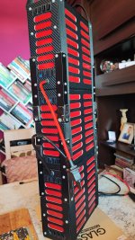
Hi, I've build an 2.8kw 24s8p battery (three 8s8p in series so I can charge them in parallel with hobby charger so no bms, for a paramotor project, using 21700 Samsung INR 40t3 4000mA, 35A, new cells from the well known company in NL.
Tested four of them from 2.5 to 4.20v and got 4.050 - 4.128mA in.
I didn't know about copper nickel sandwitch method so I've used 0.15x10mm pure nickel strip on the parallel groups on which I pre soldered 14awg wire for series connections.
For main output wires I used 8awg and QS8 antispark connectors, for series between packs I used 8awg and AS150 bullet connectors.
IMG_20230223_214818.jpg
IMG_20230227_123502.jpg
IMG_20230227_105703.jpg

IMG_20230321_160100.jpg

IMG_20230318_095120.jpg

IMG_20230430_211501.jpg

IMG_20230829_122056.jpg

The load during level flight is 3.8kw, 5-6kw for climbing and 7-10kw takeoff. Tests and flight time so far around 27min, 3.5v/cell resting.

Long story short, at full power, 17kw the voltage drop is huge like 20v that is from 98v 4.15/cell to 78v 3.2v/cell. Which is not normal because a similar paramotor that uses even smaller batt like 24s6p molicels, instead of 8p, didn't report such voltage drop.
Also the temperature after 27min (from 4.15v to 3.5v) went to 55C, at an average of 5kw load, 60A, 7.5A/cell. The cells are rated to go to 44C at 10A.
I've used a cheap spot welder, was my first time, the welds are not that strong and I didn't avoid the middle as I should.
Do you think I have considerable losses somewhere? Or why this huge voltage drop? I was told that it could be the weak welds, the many soldering points or the nickel in parallel.
I was adviced to mount a thermometer probe on the nickel. ( I can't use the battery case open and check.)

If it's the nickel in parallel, could I weld another one on top or even 0.1 copper with steel plated nickel patches or is not necessary on the parallel?
82854209be04be17cc96091bddeebedb018dcd7b.jpg

I've worked a lot at this project and would like to use the cells to their fullest and not overheat them.
Thank you!
First flight link here
 

Attachments

  • IMG_20230829_122056.jpg
    IMG_20230829_122056.jpg
    3.1 MB · Views: 1
Can you setup some (logging) voltmeters on the pack to measure a few things during load?

If so, I'd put a couple on the interconnects between cells (both series and parallel) in different places in different cell groups, and then also put a couple across the cells in different parallel groups, and a couple across the inter-pack connections (with the actual connections for all these at the cell can itself, and using at least two simultaneous measurements for each test so you can be more sure it's a consistent problem across the pack; if the measurements are different on differnet interconnects and different groups then there is more of a problem with specific ones, rather than a general issue).

Wherever there is voltage rise across an interconnect, there is high resistance.

Wherever there is voltage drop across a cell group, there is high resistance.

Temperature sensors would need to be all over the pack to tell you where the heating is, or you would need to use FLIR to "see" it directly. One sensor would tell you what the heat in that spot is, but not what the pack as a whole is doing. You can use one sensor and move it around all over the pack for different test runs, but it could take a long time to get enough useful data.


Regarding the pack properties: Did you test the cell resistances?

I see a capacity charging test, but no discharging measurements. If you did this test, what capacity did you get, and what current did you test at to get the capacity measurements for discharging? (If you didn't cell-level test for this, you should, and you should test at the current you will be using them at, or you won't get an applicable measurement).

This page is for the original version of the cell (where yours seems to be a third version)
They haven't tested the newer versions for comparison, but this older one has TERRIBLE voltage sag at high currents, which means a lot of power wasted as heat inside it.


Also, you say that power usage is 7-10kw takeoff, but then you say full power is 17kw, which doesn't make sense, since takeoff should take much more power than any other time for your application.

You've also listed this as a 2.8kw 24s8p battery, but if it's only a 2.8kw battery and you're using it at several times it's rated power level then it's no surprise it can't do the job you are asking of it. Hopefully you've just made a mistake in terminology or calculation for the 2.8kw part. ;)


17kw the voltage drop is huge like 20v that is from 98v 4.15/cell to 78v 3.2v/cell.

If you are seeing 17kw power draw, sagging down to 78v, that's 218A. For an 8p pack, that's 218A / 8 = 27.2A per cell. If these cells perform like the original version at that link above, that's probably about what to expect from them.

Keep in mind that a cell's rating for current is the max it is guaranteed to do for some specified time period under certain conditions without damage, not what it can be run at for best performance and efficiency.

To get better efficiency you have to have a lot less load on a cell--how much less load depends on the specific cell and the conditions it's being used under.
 
So at 17kw, you are at about 220A? 27-28A per cell, 0,95V voltage drop. That would mean about 35mOhm, sounds high.
Do the cells stay balanced under load and are they balanced after a ride?
At the begining of the ground test, with freshly charged battery 99v I went to full throttle. In three seconds the 8s voltage alarms set at 3.3v went on. The coulometer screen showed 17kw and 175A at 97v. I imediately stoped the motor. Reset the alarms at 2.9v and continued by simulating a flight at loads between 4-6kw until, after 27 min the temperature sensors placed on the middle cell of each pack went on at 55C and I stoped the test. If we take the nominal 88v that translates to 45A(5.6A/cell) for 4kw and 68A(8.5A/cell) for 6kw. And this 5.6 - 8.5A/cell builded 55C temp.
How the cells are under load I don't know, and they are like 3.70 to 3.73 all of them after flight. Tested with a volt metter.
 
Last edited:
Can you setup some (logging) voltmeters on the pack to measure a few things during load?

If so, I'd put a couple on the interconnects between cells (both series and parallel) in different places in different cell groups, and then also put a couple across the cells in different parallel groups, and a couple across the inter-pack connections (with the actual connections for all these at the cell can itself, and using at least two simultaneous measurements for each test so you can be more sure it's a consistent problem across the pack; if the measurements are different on differnet interconnects and different groups then there is more of a problem with specific ones, rather than a general issue).

Wherever there is voltage rise across an interconnect, there is high resistance.

Wherever there is voltage drop across a cell group, there is high resistance.

Temperature sensors would need to be all over the pack to tell you where the heating is, or you would need to use FLIR to "see" it directly. One sensor would tell you what the heat in that spot is, but not what the pack as a whole is doing. You can use one sensor and move it around all over the pack for different test runs, but it could take a long time to get enough useful data.


Regarding the pack properties: Did you test the cell resistances?

I see a capacity charging test, but no discharging measurements. If you did this test, what capacity did you get, and what current did you test at to get the capacity measurements for discharging? (If you didn't cell-level test for this, you should, and you should test at the current you will be using them at, or you won't get an applicable measurement).

This page is for the original version of the cell (where yours seems to be a third version)
They haven't tested the newer versions for comparison, but this older one has TERRIBLE voltage sag at high currents, which means a lot of power wasted as heat inside it.


Also, you say that power usage is 7-10kw takeoff, but then you say full power is 17kw, which doesn't make sense, since takeoff should take much more power than any other time for your application.

You've also listed this as a 2.8kw 24s8p battery, but if it's only a 2.8kw battery and you're using it at several times it's rated power level then it's no surprise it can't do the job you are asking of it. Hopefully you've just made a mistake in terminology or calculation for the 2.8kw part. ;)


17kw the voltage drop is huge like 20v that is from 98v 4.15/cell to 78v 3.2v/cell.

If you are seeing 17kw power draw, sagging down to 78v, that's 218A. For an 8p pack, that's 218A / 8 = 27.2A per cell. If these cells perform like the original version at that link above, that's probably about what to expect from them.

Keep in mind that a cell's rating for current is the max it is guaranteed to do for some specified time period under certain conditions without damage, not what it can be run at for best performance and efficiency.

To get better efficiency you have to have a lot less load on a cell--how much less load depends on the specific cell and the conditions it's being used under.
-Don't know about the voltmeters because I already have many things on this battery that I can safely carry in flight.

- I didn't have the knowing or devices to test one cell for resistance as the ISDTT8 charger shows impedance only for two or more cells.

-The capacity test was done at small discharge/charge curent of 1.5A.The capacity was between 4050-4128mA. Later I did a discharge test at 8A to three cells spot welded in series with the same nickel.
Initial temp 23C, initial voltage 12.88v that droped at 11.4v after start.
-After 10 min nickel 32C, cells 35C, 10.2v, 3.41v/cell.
-18min nickel 37C, cells 41C, 3.2v/cell
-22min nickel 40C, cells 46C, 9v, 3v/cell. End test.
And these temperatures in open air on three cells. If you put 64(8s8p) enclosed together..not much from 46C to 55C.
IMG_20230903_070730.jpg

- I have 68kg, 110 with all the gear and wing. I can take off at 7-8kw, that's what I saw on the lcd before leaving the ground, what others that have 90kg and 140kg total need just to stay airborne. The full throttle was just for seconds of testing what the rig can do. Others use it to climb fast, I've never used it in flight yet, only at ground test. Basicaly I don't need it, but the cells should handle it. The SP140 from openppg where I've got my info along the way and posted my project, uses a 4kw 24s11p and also a lighter 2.2kw 24s 6p with molicells, they both can do full throttle of even 20kw no problem(identical engine as mine). Thus my concern...

- Regarding using a 2.8kw battery several times it's rated power, I'm not sure I understand. Because, as gently as I am with the throttle I don't know many to be and have read a lot of flight reports.
Others take off at full 20kw and go below 6kw only if they want to descend.
I went to full 17kw for seconds, never intended more. Thanks!
 
Last edited:
Amberwolf is probably correct in his analysis, that just because the cells are "rated" for 35 amps max discharge each, doesn't mean that its the most ideal circumstance. The discharge tests he linked show some massive voltage sag at this discharge level, sorry.

That said, I've never before seen your method for the series connections, using pre-soldered nickel strips. Might have to steal the idea, it definitely has its advantages!
Well I saw 175A for seconds..devided to 8 is 21.8A on 35A rated cells.
The Molicel 24s6p of the SP140 electric paramotor does 20kw because has the same motor as mine. At 88v that power means 227A from 6cells is 37.8A/cell.
If I hadn't heard that Samsung are good cells would never consider them. Well how good are they if molicel rated at 45 can hold 38A but Samsung rated at 35 can't hold 22A.
I should have paid one euro per cell plus and get the Molicel 😩
Oh! Please do tell about the atvantages of pre soldered nickel strips because no one mentioned any. 😕
 
Last edited:
Oh! Please, please do tell about the atvantages of pre soldered nickel strips because no one mentioned any. 😕 And since a few days that my batt analisys started I feel like sh...t. After ten months of doing and investing in nothing else than in this project
Don't feel bad! You were still able to build your own flying vehicle. That's impressive on its own.

What I mean is that it's not easy to spot weld packs for high amps. The copper/nickel sandwich is one way, but it requires a pretty strong spot weder. Custom cut copper busbars with nickel connections for the cells are a great solution, but expensive. I like your method because it focuses one beefing up the current capabilities of the series connections, rather than parallel, and it could use any old wire lying around, and uses standard equipment. I will say that one of the weakness of soldered connections is that they're more susceptible to vibratory degradation, more likely to break off than spot welded connections, and vibrations are something you see a lot on EVs... so take that under consideration.

What did you use for the box? Carbon fiber sheets, or a different material with carbon-fiber-looking covering for aesthetics?
Well how good are they if molicel rated at 45 can hold 38A
Even high-amp molicels admit decreased lifespan if continuously pushed to their max discharge rating.
 
I think that the problem might be the portions of the parallel nickel between the series connections and the cells. The high curent travels through the series connections which I have seven, only six at pack ends. Then to get to the cell, it gows through a few mm of 0.15x10mm nickel strip. If we are talking 175A that's 21A that gows through that piece of nickel. Which, acording to one graph would be fine since 14A and even 21A are ok for 0.15x10mm nickel but acording to the next graph only 6A are ok...guess which graph I hope reflects the thruth 😃 I'm guessing the one with 6A.

Screenshot_2023-09-03-23-03-50-494_com.miui.gallery.jpg


IMG_20230829_095714.png
IMG_20230903_232133.jpg
 
Don't feel bad! You were still able to build your own flying vehicle. That's impressive on its own.

What I mean is that it's not easy to spot weld packs for high amps. The copper/nickel sandwich is one way, but it requires a pretty strong spot weder. Custom cut copper busbars with nickel connections for the cells are a great solution, but expensive. I like your method because it focuses one beefing up the current capabilities of the series connections, rather than parallel, and it could use any old wire lying around, and uses standard equipment. I will say that one of the weakness of soldered connections is that they're more susceptible to vibratory degradation, more likely to break off than spot welded connections, and vibrations are something you see a lot on EVs... so take that under consideration.

What did you use for the box? Carbon fiber sheets, or a different material with carbon-fiber-looking covering for aesthetics?

Even high-amp molicels admit decreased lifespan if continuously pushed to their max discharge rating.
I've made the box from 1.5mm aluminium and bolts..lots of bolts. Made lightening holes and covered in carbon wrap to take away the garage build looking...
IMG_20230302_185419.jpgIMG_20230328_120556.jpgIMG_20230325_173912.jpgIMG_20230404_144748.jpgIMG_20230406_205052.jpgIMG_20230411_184110.jpg
 
  • Brainy
Reactions: NSP
-Don't know about the voltmeters because I already have many things on this battery that I can safely carry in flight.
<snip>
Later I did a discharge test at 8A to three cells spot welded in series with the same nickel.
Initial temp 23C, initial voltage 12.88v that droped at 11.4v after start.
-After 10 min nickel 32C, cells 35C, 10.2v, 3.41v/cell.
-18min nickel 37C, cells 41C, 3.2v/cell
-22min nickel 40C, cells 46C, 9v, 3v/cell. End test.
And these temperatures in open air on three cells. If you put 64(8s8p) enclosed together..not much from 46C to 55C.

With that same test setup, you can use it to test the voltage drop under load. That will tell you more about what is happening, because it will directly tell you where the power loss is happening, where the waste heat is being generated and by what. Then you can work on fixing it.

Setup a load that will draw (measured by the multimeter if it can read that high, or an RC wattmeter or coulometer otherwise) the same per-cell current from it that your system does from your battery. Meaning, since it's a 1p setup, 1/8th of the total current that your system does at various load conditions. It is important that you test at these currents to find out what is going on, since you can't test the pack itself this is the closest substitute you have.

The load can be heater elements, big coils of wire, etc; you can use ohm's law to calculate the resistance required to draw a certain amount of current at a certain amount of voltage. In this case you would use the version: Ostrich (ohms) sees (equals) the Vulture (volts) over (divided by) the Anteater (amps). I would recommend using the nominal cell voltage (3.6-3.7v) times the number of series cells (3) as your voltage in this calculation.

If you don't have a high enough load, you can't simulate actual conditions, and you can't know what the pack is actually doing inside in flight. Extrapolating from lower currents gives a guesstimate, but you would need multiple tests at different currents from the lowest to the highest you can do to create a curve of measurements to then extrapolate the curve to higher currents than that...but it may not be accurate, as the cell's actual behavior could be different as currents increase. (so it might look ok, and end up really being very different). But at least it would be some specific data, which ATM you don't have.

Because your pack's series connections are wires, not nickel, then you will need to add in place of one of the series nickel interconnects, in the same way you did so for your pack, a length of wire identical to what you used in the series pack connections. That way you can simulate the series pack connection to test voltage drop. It can't be one of the wires you already have on the ends of the pack, because you need it to be the same length and affixed in the same way at each end to the cells as your pack's series connections, so you should cut the nickel interconnect in the middle, and solder the wire across the gap.

Then measure the voltages across every series connection, including that from the cell can to the strip (across the weld), and every cell, without the load, then while under load and then again without the load.

If there are voltages across any connections, they are too high a resistance and need to be fixed. You can change the connections out for lower resistance versions, or parallel more connections, etc.

If there are voltage drops across the cells, they are going to waste the difference in voltage from loaded to unloaded as heat inside the cells themselves. You can parallel more cells to help with this (my guess is three or four times as many cells as you have now), or you can use different cells actually capable of the currents you need, that have much lower internal resistance.


- Regarding using a 2.8kw battery several times it's rated power, I'm not sure I understand.

If something is rated for a certain amount of power, then you should not exceed that power. Doing so means that you are overloading it. ****

If the battery is rated for 2.8kw, then you can't safely use it above that. Definitely not at 17kw.

If the 2.8kw is just a wrong term (kw instead of kwh), then it's important to note the distinction, because one of them is a measure of power, and the other a measure of capacity, and using the one to denote the other is just going to confuse things.

****many things can exceed rated power for a very short time, but with batteries it can be dangerous, as you may overheat cells and damage them in ways you can't even know have happened, which can then lead to fires....
 
Back
Top