Help needed using a AC DC converter.

Not sure I understand the question. Do you mean if the CA can accept DC, or if the samsung/apple converter can accept DC?

And if the latter, you could just hook it up to your battery (no need to hook it up to a CA, unless you're measuring the converter's power usage).


As far as using various converters, well, you can use many devices that are labelled for 100VAC-240VAC on DC even at much lower voltages, though some of them will need higher start voltages than they'll run at once started. Even many CFLs will run on your ebike pack (I used to use them for headlight and tailight).

Some stuff doesn't work, but you can find lots of them to try at Goodwill and the like, for next to nothing, or on Freecycle for nothing. Maybe even at yard sales, etc.

If you look around the forum there are a lot of threads and posts about this, with various suggestions on how to mount, connect, modify, etc., if you need to.


As far as specific chargers go, I have had the least luck with Apple branded chargers and power supplies, but I haven't got anythign recent to try out.

I have had at least one 12V + 5V output unit work off a 58V-charged pack; it was off an external harddisk of some type AFAIK. Don't remember the brand.
 
amberwolf said:
Not sure I understand the question. Do you mean if the CA can accept DC, or if the samsung/apple converter can accept DC?

And if the latter, you could just hook it up to your battery (no need to hook it up to a CA, unless you're measuring the converter's power usage).

I meant, can the Samsung charger accept DC?

Anyway, so I wired my Samsung Galaxy S2 AC wall charger to the power out on my CA, and it worked!!! :D
So I just need to make a cable with a female 5.5x2.1 on one end and a wall socket on the other end! Should have just done that from the start so I could test "wall warts" (as you guys call them) without taking off the plug. This almost seems too good to be true! So just to confirm- I'm not going to damage my phone, charger or CA if I leave it connected?

amberwolf said:
I have had at least one 12V + 5V output unit work off a 58V-charged pack; it was off an external harddisk of some type AFAIK. Don't remember the brand.

Yeah I was trying to get a dual voltage (12v+5v) converter to charge my phone a couple of days ago but I couldn't get it to work. But I'm guessing thats because its a Samsung which needs its data pins messed about with so it will draw the power. Seemed like a ball ache so decided to try using a Samsung charger instead- much easier! I don't really need 12v anyway. :D
 
izeman said:
The CA power output is NOT meant to power those power supplies. Look into the manual to see how much current you can draw.
Why don't you connect the charger DIRECTLY to the main battery?

I thought the CA puts out pretty much whatever the battery puts out directly? Is that wrong? If its okay to connect an AC converter to the battery then why isn't it okay to connect it to the CA?
 
DC Power Cable
There is an additional short cable from the device terminated with a
5.5x2.1mm power plug. This is connected to your battery voltage and
is protected by a 500mA polyfuse
. It can be used for powering the
Lumenator headlights or other devices (such as DC-DC converters,
Analoggers) that run off your full battery voltage and draw less than 0.5
amps. It can not be configured as a 12V output.
This cable comes with a rubber cap to protect against corrosion or
inadvertent short circuits. It is important to leave the rubber cap on
the plug when you don’t have it connected to a device, especially if
you are running more than 48V.

0.5A is plenty unless it's a BIG charger

And obviously you need a switch to turn all this off so you don't drain your battery if left for a month or two.
 
Gregory said:
DC Power Cable
There is an additional short cable from the device terminated with a
5.5x2.1mm power plug. This is connected to your battery voltage and
is protected by a 500mA polyfuse
. It can be used for powering the
Lumenator headlights or other devices (such as DC-DC converters,
Analoggers) that run off your full battery voltage and draw less than 0.5
amps. It can not be configured as a 12V output.
This cable comes with a rubber cap to protect against corrosion or
inadvertent short circuits. It is important to leave the rubber cap on
the plug when you don’t have it connected to a device, especially if
you are running more than 48V.

0.5A is plenty unless it's a BIG charger

And obviously you need a switch to turn all this off so you don't drain your battery if left for a month or two.

Well this one says its 0.7A. So that would make it unsafe to connect to the CA?
 
madnomad said:
Well this one says its 0.7A. So that would make it unsafe to connect to the CA?

It really depends what you're attempting to power with it. If delivering maximum output mA it'll likely use all .7mA and blow the CA fuse. Kinda playing a guessing game with moving goal posts, eh?
 
Are you saying it OUTPUTS 5V at 700mA?

If so P=VI, 5Vx0.7A=3.5W output. Not sure how efficient these SMPS are at voltages lower than designed. Add a bit for those inefficiencies so it may be 5W input.

At 40V INPUT (have you said what pack voltage is?) to get 5W you need the CA to supply 5W/40V=0.125A

I think it will be fine.
 
Gregory said:
If so P=VI, 5Vx0.7A=3.5W output. Not sure how efficient these SMPS are at voltages lower than designed. Add a bit for those inefficiencies so it may be 5W input.

At 40V INPUT (have you said what pack voltage is?) to get 5W you need the CA to supply 5W/40V=0.125A

I think it will be fine.
Ya. These are switcher supplies (not linear regulators) so they can supply more current at lower voltage than consumed on the input side at higher voltage. Design considerations will limit things very much more than the simple math at 100% efficiency would suggest, but 2x the input current would not be surprising. Take a look at the label on your charger to get some notion of the actual input current requirements at the mains voltage. It will require more at a lower input voltage, but it will serve as a general indicator.

The CA has no idea what is plugged in - the Aux Power port will run any device that requires battery voltage - it's just a straight feed through the CA except for the fuse. No problems there.

In the worst case, the polyfuse will interrupt the current if you draw too much but will reset after you disconnect the load. This is as intended and there is no downside to it. So - no worries to try this to see if your charger wants too much power.

madnomad said:
Anyway, so I wired my Samsung Galaxy S2 AC wall charger to the power out on my CA, and it worked!!! :D
This is good news! Thanks for posting back - I'm sure that there are other ES members who will appreciate your test results.

BTW - unless there has been a production change, Justin reported some time back that the V3 uses a 1A polyfuse.
 
:twisted: Sorry for being a bit late to the party on this one, but could not resist :twisted:

It could be that 56 volt DC is too low for it to start. I have never had much success with getting many to run below about 60 volts.


Kiriakos GR said:
The Greek is professional industrial electrician and electronics is his daily job.
One blurred picture is no proof.
AC powered converters expect AC mains so to even start working.
Kiriakos GR said:
AC powered converters expect AC mains so to even start working.

Utter bullshit. They may be some that do, but on the whole most of these SMPSU's we encounter on a daily basis will happily run off DC. But I'd not be so certain to make a blanket statement of that fact as there could be some out there that do require AC only to run. I am not a professional so I don't know for sure :roll:

If you are as professional as you say, you'd know that these Switched mode PSu's generally have a bridge rectifier as the front end...

To those that don''t know (because they are not professionals) a bridge rectifier converts AC in to DC.

So If you just feed in DC ..it just passes the DC straight through the rectification diodes to the vibrator / transformer circuity and all works exactly as if AC had been running it.


56 volt may be a bit low though...if you wanted to get fancy you could try bypassing the bridge rectifier section and feeding the DC voltage in on the other side of it, so loosing the voltage drop of the input rectifier diodes...not a lot I know, you will probably only gain 1-1.4 volts ...but n marginal cases that may just be enough to power up the rest of the circuit..
 
Kiriakos GR said:
... it is not that hard to discriminate Angels from Demons among professionals...

I am certain that we are all in total agreement about that - it IS easy to tell them apart.... :lol:

  • Kiriakos GR said:
    This is AC Mains powered and not DC to DC compatible.
    A quick Google turns up this white paper that discusses this topic (see p9 "Powering Equipment and Appliances with DC").
    The paper is a supporting reference for a Wikipedia article that claims:

    Wikipedia said:
    A SMPS [switch mode power supply] designed for AC input can usually be run from a DC supply, because the DC would pass through the rectifier unchanged.

Read More - Write Less.
 
teklektik said:
BTW - unless there has been a production change, Justin reported some time back that the V3 uses a 1A polyfuse.

Excellent info, my quote with the 500mA was from the 2.3 manual. My apologies for being too lazy to reference it!
 
As soon as my wife finishes dinner she will film me electrifying a cree light with the main leads on a 125v bike using a 9v 2a wall wart. also I tested the discharge voltage of the ca luminator plug. It puts out what the mains do as far voltage is concerned. I have a ca 3 backup in case I blow something but I'm tempted to run off the ca to a converter then to the lights.

Here is the vid of the mains going thru a 9v2a AC to DC converter to the bike light Edit: I just saw the post above.Does that means I would blow the ca polyfuse with this converter if the light drew more than .5 amps because I have a ca 2.3?

[youtube]LYQCuYgKZ-0[/youtube]
 
100volts+ said:
Does that means I would blow the ca polyfuse with this converter if the light drew more than .5 amps because I have a ca 2.3?[/b]
If your converter's input (not the light itself) draws more than that, then yes.
 
the wall wart shouldn't draw that much to power the light if 125v are going into the converter. Even .5amp would output 60 watts right? PS How hard is it to change a polyfuse?
 
100volts+ said:
How hard is it to change a polyfuse?
teklektik said:
In the worst case, the polyfuse will interrupt the current if you draw too much but will reset after you disconnect the load. This is as intended and there is no downside to it. So - no worries to try this to see if your charger wants too much power.
There is nothing to replace - it resets automagically.
BTW - nice wallwart/light demo. Thanks!
 
teklektik
Did you help develop the CA? You are the one who wrote the unofficial user guide to CA3 aren't you.
 
Not a developer - just an interested beta-tester.
Ya - I did the Guide. It sort of evolved from basic HowTo notes in a 2012 post to the present manual. Kind of a fun little project... :)
 
teklektik you are a bloody legend for writing that manual and providing free technical advice on ES.

100volts+ said:
125v bike using a 9v 2a wall wart

There's no need to guess, you already have the set up so just put an ammeter between the battery (in series with one of the wires) and wall wart and measure it.
 
teklektik said:
Take a look at the label on your charger to get some notion of the actual input current requirements at the mains voltage. It will require more at a lower input voltage, but it will serve as a general indicator.

The CA has no idea what is plugged in - the Aux Power port will run any device that requires battery voltage - it's just a straight feed through the CA except for the fuse. No problems there.

In the worst case, the polyfuse will interrupt the current if you draw too much but will reset after you disconnect the load. This is as intended and there is no downside to it. So - no worries to try this to see if your charger wants too much power.

Awesome, so knowing the fuse resets, I decided to try a different Samsung charger rated at 2a, and its absolutely fine charging my Samsung Galaxy S2 with my 58v battery. I guess it might blow the fuse if you try to charge a tablet though.
EDIT: Actually I've just noticed that 2A is what it puts out. It's takes 0.35A, so no problem there then.

Here's a pic of the label:

DSC_0031.JPG


It's nice because you can take off the pins to make it more compact:

DSC_0032.JPG


And the earth pin folds down. Here is my bodge job wired to a 5.5x2.1 just to test it:

DSC_0034.JPG


Now I need to buy a couple of those connectors for connecting wires to pins, like you see inside computers. Does anyone know what they're called?
 
G-
Thanks for the kind words - appreciated! :D

M-
madnomad said:
... its absolutely fine charging my Samsung Galaxy S2 with my 58v battery.
Now I need to buy a couple of those connectors for connecting wires to pins, like you see inside computers. Does anyone know what they're called?
Excellent news. Looks like this is coming together.

As far as I know, you are looking at some proprietary contacts there. There are several ways to go after this but an important concern is an effective cable strain relief.

I would approach this by soldering directly to the existing contacts and then using E6000 glue to gorp the wires and cable into place. This glue or derivatives are widely available in the US as part of a family of products named "xxxx Goop/Goo" (e.g. "Shoe Goo") and sticks to almost anything, is really thick, and dries to a tough, slightly rubbery, nearly indestructable blob (think: build up and replace sneaker soles). This is my GoTo glue for semi-flexible non-brittle fastening like this.

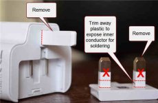
I might first try modifying the removable adapter plate by trimming the prongs and exposing some inner conductor for soldering. This avoids messing with the spring-loaded pins on the adapter proper. After soldering on the cable leads, you could put a small zip tie tightly on the end of the cable sheath so even if the glue did not adhere to the shealth too well, it would mechanically retain it by being molded around the zip tie. Then blob up some glue over the prong stubs and cable - might take two layers. If this goes well, you could trim off the Gnd prong and just snap the plate into place.


DSC_0032a.JPG
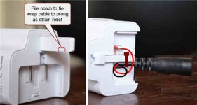
An alternative (either first try or second attempt if the idea above goes poorly) is shown below that involves tinning the adapter contacts, soldering the cable leads directly to them, then zip tying the cable to the Gnd prong. Depending on the dimensions of the Gnd prong and cable, you might also notch/undercut the prong out to the tip so the cable could be centered under the prong and zip tied to the remaining top part of the prong. (These giant UK plugs are a little alien to me but this might work). Finish up by folding down the Gnd prong and flooding the recess with glue to embed the prong + wiring/cable and insulate the soldering points.

DSC_0034.JPG
Your tools and skills are your guide on this packaging step - which is always sort of an annoying part of these little adaptations....

Anyhow - just a few thoughts.... :D
 
Nice idea! I'll probably do that in the future, but for the time being while I'm trying out loads of different AC-DC adapters, I decided to go down this route:

DSC_0039.jpg


Unfortunately I blew up my 8.4v Cree bike light today so I'm using my USB powered one now. I stupidly put 12V 1.7A into it and it was obviously too much. Think I'll stick with the USB light for urban riding but I'm on the look out for something a lot brighter for rural use. Does anyone have any recommendations in the £30/$45 range?
 
Back
Top