Help with understanding how to pick a hall sensor

MindWorX

1 µW
Joined
Apr 7, 2024
Messages
4
Location
Denmark
Hi everyone,

I've had the fortune of getting my hands on a somewhat large amount of sensored BLDC motors from old Segways. I've been documenting them a bit on GitHub here.

Right now I'm facing an issue that the various ESCs I have at my disposal all expect a binary/digital hall sensor, but the one on these motors are analog.

To help make the motors into usable sensored BLDC motors for me, I've been looking into replacing the PCB and adding new hall sensors, but since I've never done this before I have no clue how to even approach this. I took one of the PCBs off to see how the current ones were working, and it turns out the motor has a permanent magnet on it's rotor, that is used to sense it's position. Here's how that looks.
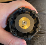
1712493265699.png

The motors have a double redundancy so they have twice the windings and twice the hall sensors, but I just need them to work as normal motors, so for me all I need is 3 hall sensors. Here is how the different pins are connected and the white dots are where the hall sensors approximately were before, which is 60 degrees apart.
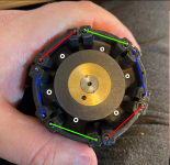
1712493745309.png

How should I approach picking the right hall sensor for this motor? Can I just pick any digital ones? Do I need to adjust the distance to get a proper duty cycle? What else should I consider? I have no specs on the magnet.

Are there alternative solutions? I did consider making an adapter board instead with some schmitt triggers to make the analog sensors digital.

I appreciate anyone that has read this far and any help I might get.

EDIT:
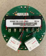
I managed to grab a picture of the existing hall sensors, but I can't find any part information.

1712495159070.png

EDIT2:
I got some help identifying the part. It appears to be the following part:
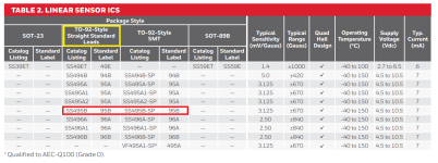
1712501911727.png
Giving some statistics like a range of ±670 Gauss. I wonder if I can just look for a digital hall sensor with the same range.
 
Last edited:
The original controller is probably using a SIN/COS sensor, and that magnet has a continuously-magnetized path along it that would give a sinewave output from the sensor that matches the poles of the rotor. It's a common way to give precise position sensing, which a self-balancing device needs.

Using a magnet system not near the stator keeps all the magnetic crap the windings put out from inducing noise in the sensors that interferes with the sensor signals and causes problems with operating the motor (especially under high load, with high phase currents).

These use a pair of sensors at 90 degrees to each other around the circle; they may not be actually physically 90, but only 90 from each other along the magnetized sinewave, so they can be much closer to make a smaller mounting board.

Because there's only two sensors, at 90 degrees, you can't directly use their output for a typical ebike/etc sensored controller, which requires three that read a 60 or 120 degree "spacing". You'd have to build electronics to convert SIN/COS to UVW / ABC. (it's likely there is a DIY project out there to do that somewhere, if not a premade product).


If you want to install halls for a typical 3-phase BLDC sensored motor controller for ebikes. scooters, etc., you'll have to install them on the stator or somewhere where they can read the rotor magnets as they pass.

Or you have to install a separate magnet ring (like the one there) but that is magnetized with opposing polarity "blocks" that match with the rotor magnets. (you can try them with the existing ring, but since it's continuously variable it may not correctly trigger the halls expecting sharper polarity flips).

Physical placement you can determine experimentally, or you can look at how various similarly-constructed stator/rotor motors have their halls placed, and put yours in the same places. There are many disassembly pics of various motors here on ES and elsewhere. Also, you can look up the various "installing hall sensors on..." whatever motor type threads for more info.


Normally these controllers expect sensors with bipolar latching open-collector outputs, like the SS41 or SS411. There are many variants with different voltage ratings, etc, normally you want one that can operate on the lowest source voltage minimum, all of them will go up to like 20-30V but most contorllers only output about 4v, maybe 4.5v, and sometimes that can be noisy or drop, so the lower VCC-min the better.
 
Last edited:
I took a peek at the linked github, and it shows a schematic for three hall sensors with inputs, but I don't know of any that have inputs, so perhaps those aren't hall sensors, or perhaps they have "one-wire" type signal lines which allow communication between them and whatever they connect to. Either way, if there are three, then either one is a redundancy backup, and all three are placed 90 from each other (so any can be SIN or COS to the one next to it, but if the middle one fails the system wouldn't work), or they aren't typical SIN/COS encoder, but some other form of analog position encoder (of which there are probably as many as the mind can imagine).

But unless they are at the 60 or 120 degree spacings from each other, their signals still won't work (even if squared-off) for the typical sensored controller types.
 
I very much appreciate your answer.

From testing I know this is using 3 hall sensors at 60 degree offsets. The reason it has 6 of them is because of redundancy, the motor is designed to essentially be controlled by two separate ESCs, so if one fails, the other takes over and if both work it has more power.

1712525738347.png
This is the analog signal I'm getting. It was rotated by hand so it's a bit jumpy and it was snapping to certain positions.

I'm fully on board with DIY'ing something for this, since I have a decent amount of these motors, so it's worth the investment in time since these are very decent motors I think.

Your point about the current magnet being "continuously variable" is exactly what I was concerned about as well, since picking a hall sensor that works binarily with this seems tricky. Replacing the magnet with a different configuration is an interesting idea. I'm mostly looking into options that doesn't require me to further disassemble the motors as I'd be concerned I can't put them back together.

I have considered adding an MCU like a small STMF0/STMF4 that could take the analog signals and conditionally emit a high/low signal. I could even make it possible to configure the thresholds for this to get the right duty cycle. It's definitely kinda over-engineered, but I imagine it could work. Or does it sound silly?

Again, really appreciate the help, been looking for places to discuss these kinds of things, this place seems great.
 
1712526897544.png

The motor is kinda split as shown here, with 3 hall sensors on the left and 3 pins to power the coils. The relays are essentially the center point of wye connected coils. I hope this makes sense. The motor can essentially be powered and run purely off what is on one side of the red line. I have done this, just without sensors.
 
From testing I know this is using 3 hall sensors at 60 degree offsets. The reason it has 6 of them is because of redundancy, the motor is designed to essentially be controlled by two separate ESCs, so if one fails, the other takes over and if both work it has more power.

View attachment 350667
This is the analog signal I'm getting. It was rotated by hand so it's a bit jumpy and it was snapping to certain positions.

The snapping is probably the rotor magnets cogging to the stator teeth, which is normal for a PM motor. If each one of the "steps" corresponds to a rotor magnet "width", then those signals can't be used directly even with squaring-off, because your controller will expect pulses that correspond directly to the rotor magnet polarity changes.

If you want a more representative signal, drive the motor with another motor (drill, etc) or if you have one of the complete segway drivetrains you can spin the wheel itself which will backdrive the motor much more smoothly via the gearing.


Your point about the current magnet being "continuously variable" is exactly what I was concerned about as well, since picking a hall sensor that works binarily with this seems tricky. Replacing the magnet with a different configuration is an interesting idea.

I don't know how to do it, but you might see if you can remagnetize the existing magnet to match the rotor magnet polarities, in "stripes".


I'm mostly looking into options that doesn't require me to further disassemble the motors as I'd be concerned I can't put them back together.

I have considered adding an MCU like a small STMF0/STMF4 that could take the analog signals and conditionally emit a high/low signal. I could even make it possible to configure the thresholds for this to get the right duty cycle. It's definitely kinda over-engineered, but I imagine it could work. Or does it sound silly?

You could probably do that. It would need to be fast enough to handle the worst-case full-speed signals from the halls. ERPM (electrical RPM) determines how fast switching has to occur in a controller to run a motor; these are motors that drive wheels via gearing, so the motor runs faster than the wheel (probably several times faster, at least).

If you have the gear ratio from these motors to the original wheels, and the ratio of the original wheel size to the size of the wheels (or whatever) you want to drive with them, and the RPM you need those to spin at, then take that number and multiply by the number of magnets in the rotor, and that's the ERPM you'll need to deal with.

Your decoder will have to be able to clearly read the analog signal steps that correspond to each magnet, and create a digital low or high on the output, in the time that ERPM leaves available to it to do so.
 
View attachment 350668

The motor is kinda split as shown here, with 3 hall sensors on the left and 3 pins to power the coils. The relays are essentially the center point of wye connected coils. I hope this makes sense. The motor can essentially be powered and run purely off what is on one side of the red line. I have done this, just without sensors.
Interesting setup. I wonder if torque is uneven driving it that way, or if it's just lower, with greater (and uneven) heating in the used half of the motor?
 
You could probably do that. It would need to be fast enough to handle the worst-case full-speed signals from the halls. ERPM (electrical RPM) determines how fast switching has to occur in a controller to run a motor; these are motors that drive wheels via gearing, so the motor runs faster than the wheel (probably several times faster, at least).

If you have the gear ratio from these motors to the original wheels, and the ratio of the original wheel size to the size of the wheels (or whatever) you want to drive with them, and the RPM you need those to spin at, then take that number and multiply by the number of magnets in the rotor, and that's the ERPM you'll need to deal with.

Your decoder will have to be able to clearly read the analog signal steps that correspond to each magnet, and create a digital low or high on the output, in the time that ERPM leaves available to it to do so.
I'm going to look into this, I have a handful of STM32F4 test boards I can play around with. Using something called DMA, I can have it continuously run samples, so I imagine it can be fast enough even with slower MCUs.

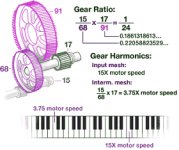
I have the original gearbox between the motor and the wheel and of course also some wheels to check the diameter. Looking at the website for the Segway it has the following picture for the gear ratio, so maybe it's just as simple as using these numbers.1712649921700.jpeg

Interesting setup. I wonder if torque is uneven driving it that way, or if it's just lower, with greater (and uneven) heating in the used half of the motor?
It's my understanding that the windings are essentially running on top of each other, so using just one set should be the same as any other motor, but I will have to see when I get it going.
 
Back
Top