
You are using an out of date browser. It may not display this or other websites correctly.
You should upgrade or use an alternative browser.
You should upgrade or use an alternative browser.
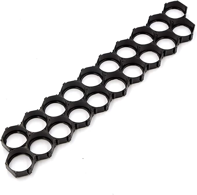
Honeycomb 21700 Cell Holders -- looking for source
- Thread starter jas67
- Start date
ichiban
100 W
Actually, you can make your own cell holders any size, any shape you like. 3D CAD, 3D printer, appropriate filament. I use PA-CF (Nylon Carbon-fiber upto ≈100 deg C working temp) for my 2 identical(mirror?) packs * 20S3P of Samsung21700-40T. They are durable, light, fit perfectly with cells, fun to make, may be cheaper than buying, last as long as your batt pack and, most importantly, your own design. Or send your design to 3D print service for a comparable price. They will finish your job in a few days.
BTW : 3D printing for complicated functional parts that actually works require a bit of mastering it. Those who are familiar the area know what I'm talking about. Actually, with proper design, we can make our own batt pack from 3D prints.


BTW : 3D printing for complicated functional parts that actually works require a bit of mastering it. Those who are familiar the area know what I'm talking about. Actually, with proper design, we can make our own batt pack from 3D prints.
ichiban said:Actually, you can make your own cell holders any size, any shape you like. 3D CAD, 3D printer, appropriate filament. I use PA-CF (Nylon Carbon-fiber upto ≈100 deg C working temp) for my 2 identical(mirror?) packs * 20S3P of Samsung21700-40T. They are durable, light, fit perfectly with cells, fun to make, may be cheaper than buying, last as long as your batt pack and, most importantly, your own design. Or send your design to 3D print service for a comparable price. They will finish your job in a few days.
BTW : 3D printing for complicated functional parts that actually works require a bit of mastering it. Those who are familiar the area know what I'm talking about. Actually, with proper design, we can make our own batt pack from 3D prints.
028.png
386570.jpg
67.png
I've thought about 3D printing, but, lack the 3D cad skills, and don't have a 3D printer.
Maybe someone on this forum would be willing to make me a set? I, of course, do not expect this work for free. I need to figure the exact configuration I'm going to use. I will likely be 2 or three sections folded over.
Is this something you'd be interested in doing for me? I'll get the specs do you, and you and quote me your labor and material costs.
Thank you!
Jay
ichiban
100 W
Not long after printing this cell holders & some other parts, I sent my Voron2.4 (3D printer) to a friend to upgrade/mod and do not expect it to be back in about a month. It will be a Rev2, reliable and fast. I really enjoy using it.
I can help you with the CAD design during my free time, and if your cell holders are not very fancy. After you receive the file, you can have it printed at any 3D printing service to you like. Printing charges should be fairly cheap. So you can save some shipping cost & time compare to shipping the 3D parts from Bangkok to you. Havn't asked yet, where do you live ?
I will post the CAD file here in case other members can be benefit from. At least, this is a way of payback from what I learned a ton here within this ES forum. After you use this cell holders for your pack, do pay it forward to others as well. We need it badly in this situation.
Hope you are OK with that ?
If so, just post detail of your cell holder layout here. I'll look into it.
In the future, should you need to do some mod/design re anything, just think about 3D print first. Fast, fun, cheap and very practical. It is a good time for anyone to start learning 3D printing, if not done yet. Tons of info on youtube and tons of potential. I strongly recommend it. After you play with it for a while, technical parts will become easier with your design by avoiding the complication, high cost, slow, and etc. You will enjoy it.
Some other parts I designed & already printed for this new bike :
+ 24P magnetic cadence sensor, Grin did not have the size I need for my DH bike and cannot find it anywhere. So need to 3D print it out of Polycarbornate CF. Very strong as a plastic, cannot destroy it by hand. Almost feel like a CNC machined plastic parts.
+ Spacer to separate/offset chainring & crankarm, approx 15-mm thick. This is to prevent chainring to rub with the thick batt case while chainline remains intact. Very strong as well.
+ etc...
ichiban
100 W
Before I forget, how much do you think this design work will cost ? First amount that come up on your mind...don't read the next line yet...
Do not send it to me. Donate it to your community that you think appropriate.
Wish your good deed bring you and the family happiness !
Do not send it to me. Donate it to your community that you think appropriate.
Wish your good deed bring you and the family happiness !
ichiban said:Not long after printing this cell holders & some other parts, I sent my Voron2.4 (3D printer) to a friend to upgrade/mod and do not expect it to be back in about a month. It will be a Rev2, reliable and fast. I really enjoy using it.
I can help you with the CAD design during my free time, and if your cell holders are not very fancy. After you receive the file, you can have it printed at any 3D printing service to you like. Printing charges should be fairly cheap. So you can save some shipping cost & time compare to shipping the 3D parts from Bangkok to you. Havn't asked yet, where do you live ?
I will post the CAD file here in case other members can be benefit from. At least, this is a way of payback from what I learned a ton here within this ES forum. After you use this cell holders for your pack, do pay it forward to others as well. We need it badly in this situation.
Hope you are OK with that ?
If so, just post detail of your cell holder layout here. I'll look into it.
....
I am in the USA, so, yeah, getting it printed here makes a lot more sense. I have a few friends at work (all Mechanical Engineers) who do 3D cad work, some also for fun outside work, and at least one that has a 3D printer at home. So, I might be able to get one of them to do the cad work, and also the printing. I will certainly share the models/drawings and any knowledge/lessons learned from this build with this forum.
What diameter did you use for the cell holes? I'd assume that I want a little clearance for thermal expansion?
Just some info for you and the others who might be watching this, don't expect fast progress. I have VERY little free time in the best of times, but, right now is even worse, as where I work, my dept. manager left, his replacement hasn't been onboarded yet, so, I'm doing his job as well as my own.
FWWI, I'm an electrical & software engineer (EE degree, my job is mostly software, but, I do get to dabble in hardware from time to time, and certainly have good EE knowledge, LOL).
For the curious, the specs of the build are:
160 Samsung 40T 21700 Cells, 20s8p
Daly BMS 20S 150A
The current top contender for cell interconnect is 0.2mm X 30mm nickel, which is a good width to serve as both parallel and series connections in one. I'll likely use wider strip at the connections where the fold will be between the layers of the build (2 to 3 layers, not sure which yet).
ichiban
100 W
jas67 said:ichiban said:Not long after printing this cell holders & some other parts, I sent my Voron2.4 (3D printer) to a friend to upgrade/mod and do not expect it to be back in about a month. It will be a Rev2, reliable and fast. I really enjoy using it.
I can help you with the CAD design during my free time, and if your cell holders are not very fancy. After you receive the file, you can have it printed at any 3D printing service to you like. Printing charges should be fairly cheap. So you can save some shipping cost & time compare to shipping the 3D parts from Bangkok to you. Havn't asked yet, where do you live ?
I will post the CAD file here in case other members can be benefit from. At least, this is a way of payback from what I learned a ton here within this ES forum. After you use this cell holders for your pack, do pay it forward to others as well. We need it badly in this situation.
Hope you are OK with that ?
If so, just post detail of your cell holder layout here. I'll look into it.
....
I am in the USA, so, yeah, getting it printed here makes a lot more sense. I have a few friends at work (all Mechanical Engineers) who do 3D cad work, some also for fun outside work, and at least one that has a 3D printer at home. So, I might be able to get one of them to do the cad work, and also the printing. I will certainly share the models/drawings and any knowledge/lessons learned from this build with this forum.
Yes, that's what friends are for.
What diameter did you use for the cell holes? I'd assume that I want a little clearance for thermal expansion?
ID ∅21.28mm is what I found tight and manageable to put the cells in. The first cells holder is OK, but the 2nd side I had to use my body weight to force 30 cells in altogether. That did not hurt the cells skin unless you re-insert the cells in/out many times. You would want it to be tight fit rather than just-slide-in since plastic always yield a little especially for PA-CF in my case. It is tough & a little flex, weather proof - one of the strong 3D print filament fit for functional parts. But not all 3D printers can print PA-CF. FDM 3D printer is not like paper printer that you just hit enter and your work will come out beautifully. It still in the stage of early film-camera that you will have to manually adjust everything yourself, so the user need some skills to get a good print out of it. Years from now, we will get a point&shoot conveniences like mobile phone camera now.
After I put everything together, the pack is quite solid given that I made it thin-wall and compact - similar to your honeycomb. Still some space left that you can put temp probe among the cylindrical cells. In case you pick some other filament, dimension might need to be altered a bit, by the last decimal digit. Make sure you pick the right plastic. High temp to start with, durability closely follows. Layer adhesion must be very very good, you don't want it to shake loose during riding. I expect mine to last as long as the battery itself.
Some advise, should you decide to 3D print your honeycomb, it will be better to have a 1-mm tall walls to physically separate the Cu/Nickel pads from each other. So when put your Cu/Ni pads into place, they will sink/secure into places without touching each other - when assembling or riding no difference. Touching of pads means very high current from cells shorting - possibly be medium xxx amps in your 8P scenario. That walls will complicate your 3D print a bit, you will need supports when printing. But it is well worth it. :thumb: :thumb:
Just some info for you and the others who might be watching this, don't expect fast progress. I have VERY little free time in the best of times, but, right now is even worse, as where I work, my dept. manager left, his replacement hasn't been onboarded yet, so, I'm doing his job as well as my own.
We all are busy nowadays. That's better than jobless ! :wink:
FWWI, I'm an electrical & software engineer (EE degree, my job is mostly software, but, I do get to dabble in hardware from time to time, and certainly have good EE knowledge, LOL).
Same here. But software is not my specialties. More fun building/designing things. Give the headache to others.

For the curious, the specs of the build are:
160 Samsung 40T 21700 Cells, 20s8p
Daly BMS 20S 150A
Mine is the same SS 21700-40T / but only 20S3P spiltted in halves >> just wanna make it compact on my bike. My regular riding is <50km 95% of the time. Aesthetics is also one thing I don't wanna skip. I can add a 2nd pack for long trip. My BMS is Jikong Active Balance BMS from IC GoGo : https://www.aliexpress.com/item/4001192978656.html?spm=a2g0o.order_list.0.0.1f131802NFptub. A member (Dui, Ni shou de Dui) on this forum recommended it. This store is one of the best selling store in this category. Bought from them several times. Should be OK. My first BMS from them is 4.5 yrs old now.
The current top contender for cell interconnect is 0.2mm X 30mm nickel, which is a good width to serve as both parallel and series connections in one. I'll likely use wider strip at the connections where the fold will be between the layers of the build (2 to 3 layers, not sure which yet).
Assume that you own / have access to a spot welder. Mine is early version of kWeld and I tested 0.2mm Cu sheet with slotted 0.15mm Ni plated steel on top (sandwich technique) at 1100 A, 120J. Looks OK to me. It might be overkill for 0.2mm Cu but why not ? It just cost a bit more considering the effort we put into this piece of art - well worth it. Plus 0.2mm Cu gives a little more strength to the assy. 0.1mm is prone to break from vibration, corrosion, etc. for the years to come. I have my Cu pads fiber laser cut to design. Then after soldering everything needed, I spray painted my Cu to prevent corrosion, before start spot-welding.
Unfortunately, during welding, I accidentally touched one of the probe to the copper pad and caused a spark. That was not supposed to happen since the welding pulse was already released and that weld was finished to 120J. The other probe was still on the welded pad. One issue that can be improved / need to be protected. kWeld now went into deep hibernation. I contact Frank and still wait for his response.
Good luck and have fun with your build !


Wow, I like those laser-cut copper plates.
Uh oh? Does that mean I can't or shouldn't get one?
I have a Sunkko 709A, which won't do 0.2mm nickel reliably without slotting it.
I'm looking for a device to punch slots, but, haven't found one yet.
I'd love to have access to a CNC laser cutter!
I also have .08mm and .15mm copper sheet. I haven't had much luck with the copper sandwich method unless I slot the copper.
Again, the problem is how to do that quickly and easily. Some sort of punch tool would be best, as a dremel with a cutting wheel is tedious.
kWeld now went into deep hibernation.
Uh oh? Does that mean I can't or shouldn't get one?
I have a Sunkko 709A, which won't do 0.2mm nickel reliably without slotting it.
I'm looking for a device to punch slots, but, haven't found one yet.
I'd love to have access to a CNC laser cutter!
I also have .08mm and .15mm copper sheet. I haven't had much luck with the copper sandwich method unless I slot the copper.
Again, the problem is how to do that quickly and easily. Some sort of punch tool would be best, as a dremel with a cutting wheel is tedious.
ichiban
100 W
Don't get that wrong. kWeld is a great machine and can weld slotted 0.2mmCu + slotted 0.15mm Ni-plated steel reliably. It is just that I made a mistake by accidentally touching one probe with an exposed pad. So high current backfired into the machine. I found that at least a diode was burst - per Frank's suggestions. And now I probably need to replace some parts that are seriously back ordered like TVS diodes (50-60 wks lead time!!). Other damages still yet to be found. I sent him some close-up pictures to investigate further. Or may be I can buy a whole new control board to replace with this damaged one.
My curiosity is that, the last weld was completed, in manual mode, that I have to step on the foot-switch to fire a pulse into the spot to be welded. How come such an outside voltage can hurt the machine that much. That means there is no protection to that. Though it is obviously a user's fault, but at least, a well-designed machine should come with that kind of safety feature. I don't think I am the first nor the last user to encounter this problem. Similar to lots of other products in the market. May be in the later version that will be equipped from factory. Have to feedback to Frank about it.
I think Sunkko is also a good machine, but targetting at a much bigger market, the mass. So they don't need very fancy or very capable machine, just cheap and can do the job so they can sell by shipload. At least, it should be a reliable machine within it range, just do its job any time we need it to. Simple.
A punch tool to make slots on Ni or Cu sheet is what a lot of us have been looking for. I have long searched for it until I quitted. Do let me know if you come across one.
ichiban said:A punch tool to make slots on Ni or Cu sheet is what a lot of us have been looking for. I have long searched for it until I quitted. Do let me know if you come across one.
I'm thinking something like this:
https://www.amazon.com/Eastwood-Gau...9Y2xpY2tSZWRpcmVjdCZkb05vdExvZ0NsaWNrPXRydWU=
But, with custom dies to do slots.
A friend of mine is a tool and die maker. I may see what he'll charge to make dies to cut a 10mm x 1mm slot in nickel and copper sheet.
ichiban
100 W
Yes, punch & die is one way to go. You have access to techinican friends that can make you that. I don't.
In my case, I chose laser cut for its accuracy, not too expensive, fast, flexibility & conveniences. Just send the laser shop our file, pay them & have them send the parts back. No trial & error. It can cut any shape I like as long as it is 2D and within ≈0.10-0.15mm accuracy >> that's acceptable.
I paid 30.- USD for mine. Took them 20 minutes to cut, they said my 0.2mm Cu is so delicate that they had to dim the power down a lot & handle with care. They prefer to cut 10-50mm thick steel !
I always avoid CNC machining, tools & dies, wire-cut, millings, molds, as much as I can because they are slow & very labor intensive = expensive, while we have cheaper alternatives. Laser cut services should not be difficult to find and not expensive. I am a life-long member of penny-wise club myself. :lol: :lol:
The 0.5-mm slits in the Cu pads serve at least 2 purposes : a) improving welding quality by forcing current to go deep through cell caps instead of bypassing via upper layers of Ni and Cu pads, and, b) as a guide for aligning pads to cells' centers. Not only for perfect alignment & weld, we are working mm-scale here, off by 1-2 mm is short circuit prone = huge current. Better be over-cautious than sorry while we still can. And that laser cut answers my needs to cut Cu pads satisfactorily.
Again, in my case, I can cover the exposed welded Cu&Ni pads with the center dots of donuts that we protect cells positve from short. Now copper pads have very minimal exposed area to be oxidised - one less thing to fail.


Above slits seem a little too big for the cell positve, yes. It was designed to fit 21700 cells not the 18650s I use here just to take picture. You get the idea.

Hope I shared here help some of you building your packs.
In my case, I chose laser cut for its accuracy, not too expensive, fast, flexibility & conveniences. Just send the laser shop our file, pay them & have them send the parts back. No trial & error. It can cut any shape I like as long as it is 2D and within ≈0.10-0.15mm accuracy >> that's acceptable.
I paid 30.- USD for mine. Took them 20 minutes to cut, they said my 0.2mm Cu is so delicate that they had to dim the power down a lot & handle with care. They prefer to cut 10-50mm thick steel !
I always avoid CNC machining, tools & dies, wire-cut, millings, molds, as much as I can because they are slow & very labor intensive = expensive, while we have cheaper alternatives. Laser cut services should not be difficult to find and not expensive. I am a life-long member of penny-wise club myself. :lol: :lol:
The 0.5-mm slits in the Cu pads serve at least 2 purposes : a) improving welding quality by forcing current to go deep through cell caps instead of bypassing via upper layers of Ni and Cu pads, and, b) as a guide for aligning pads to cells' centers. Not only for perfect alignment & weld, we are working mm-scale here, off by 1-2 mm is short circuit prone = huge current. Better be over-cautious than sorry while we still can. And that laser cut answers my needs to cut Cu pads satisfactorily.
Again, in my case, I can cover the exposed welded Cu&Ni pads with the center dots of donuts that we protect cells positve from short. Now copper pads have very minimal exposed area to be oxidised - one less thing to fail.
Above slits seem a little too big for the cell positve, yes. It was designed to fit 21700 cells not the 18650s I use here just to take picture. You get the idea.
Hope I shared here help some of you building your packs.
ichiban said:Hope I shared here help some of you building your packs.
Yes, that was all very helpful. I need to up my CAD game so I can make the files for laser cutting.
I'll have to dig around and see what shops in my local area can offer that service. As my time is quite limited, I'm not adverse to spending money that ultimately saves me a lot of time. Not having to cut the slots manually will be a time saver, and as you point out, much more precise.
Similar threads
- Replies
- 1
- Views
- 397
- Replies
- 6
- Views
- 219
- Replies
- 0
- Views
- 283
- Replies
- 16
- Views
- 914