Swytch battery 10s4p recelling in a 8x5 honeycomb

madrian

1 mW
Joined
Nov 23, 2022
Messages
12
Hi all,

I bought a bike with a Swytch kit, but the battery is completely bad. I tested the capacity, which is only 1.5Ah out of the original 5Ah. I've looked for various solutions, such as some battery packs from Aliexpress, like Aerdu. I've read both good and bad reviews about them, so it's more like a lottery. I believe the best and most reliable solution is to rebuild it myself. I already have a decent spot-welder and some electronics knowledge. In the past, I've repaired some broken connections on ebike cells, replaced BMS, rebalanced cells, but I'm not 100% confident in recelling this whole battery.

IMG_7199.jpeg

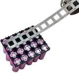
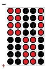
If you look at the image, the original battery uses an 8x5 honeycomb, where only 20 cells (10s2p?!) are used out of the 40. If I'm going to swap, I think it might be worth using all the empty spaces on the holder to maximize the battery's capacity.

I don't know if I can request help like this, but I would like your help with the battery layout and connections. I don't know where to start with the 8x5 design. I've watched and read many videos and articles, even for batteries like my 10s4p, but they were all different (like 4 rows in width). I would be very grateful if someone could sketch a quick drawing for this configuration. With that, I would feel more confident taking on this project.
 
If you just want to maximize the usage of the cell holder, with a 10s battery, then 40 cells / 10s is 4p.

Since the holder is 5x8, we'll call (based on your image) the 8-cell sections columns, up and down, and the 5-cell sections rows (side to side), and the side you can see we'll call the front (facing you), and the side you can't see, the back.

For 10s, you'll end up needing to do something like what they already did, but starting at a corner, and using 8 cells to a segment, four of them with positives facing you, four of them with positives facing away. The diagram below shows one possible option, using gray outlines for the interconnects on the side facing you, and green outlines for the interconnects on teh side facing away from you.

The main pack positive will be on the back bottom corner, and the main pack negative will be on the back top corner.
 

Attachments

  • pack laoyout1.jpg
    pack laoyout1.jpg
    92.8 KB · Views: 16
When I lay out a battery, I prefer to have a single column of cells facing another column. That minimizes the series current from one cell to another. The parallel connections don't matter, as current flow there is usually low. That means the best layout is a 4x10 matrix, with all 10 groups in a line.

With your 8x5, you might consider this, The top five cell groups feed each other directly, while the bottom five do the same. There is one bottleneck where all the current had to flow thru the single metal layer between the two cell groups on the right.

In principle, you can tack 4 nickle strips there to handle the extra current. I prefer to solder copper wire alongside the nickel. 14G copper can handle 15A. I would use one that straddles all 8 cells, and maybe double it for the four middle cells. The other side has no series constraints.

Of course, use all the same quality cells. Don't try to re-use any of the Switch cells. The BMS should work though, but you may want a better one.
 

Attachments

  • 1-battery copy.jpg
    1-battery copy.jpg
    96.5 KB · Views: 10
Thanks really for both of your help. I really appreciate it. @amberwolf for a great and detailed summary (I could start building on this basis) and @docw009 who optimised the layout. I don't understand the latter 100% yet because there are too many lines from the previous drawing. So I redrew it to a clean page, if I am not wrong this side is the bottom which is facing away from me, aka. side with series interconnects :

Képernyőfotó 2023-10-22 - 1.14.50.png

What should the other up side look like (facing me), with the parallel interconnects? Here is a clean drawing, I really appreciated if you could draw the parallel interconnects:

Képernyőfotó 2023-10-22 - 1.15.36.png

For the nickel strips it is enough to use the classic 0.15mm thick strips (except on the side where 4x or the copper wire)?. For the BMS: later I will change it, but for now I think I am going to use the original.

Now the last big dilemma: what cells are recommended to use in an application like this? Which are the cells that:

1) general good price/performance ratio
2) or when price does not matter, just the capacity and performance

On Nkon's website I found INR18650-MJ1 3500mAh - 10A - Reclaimed for 2,95€. Can you recommend these cells?

Thanks again for the help, they were very helpful, they couldn't help me elsewhere.
 
Last edited:
If you're going to the trouble of building a big battery for the first time, I don't think you should use the reclaimed cells. I think LG MH1's are good cells for an ebike.

Shonan rates their 8mil x .15mm strips at 7A, with 10A maximum. I figure they're not going to lie about this and have want their customers burn things up.

You have to visualize the current flow in a battery. Otherwise, I don't doubt people have short circuited entire p-groups and start fires. Figure out the backside by yourself and post it here if you want it reviewed. It might be worth making a 3S-2P battery out of reclaimed cells to teach yourself.
 
... original battery uses an 8x5 honeycomb, where only 20 cells (10s2p?!) are used out of the 40. If I'm going to swap, I think it might be worth using all the empty spaces on the holder to maximize the battery's capacity.
So it sounds like you're considering a 10s4p DIY build? Here's a 10s5p pack with LG MJ1 cells (17.5Ah, 50A, 36v, Cuboid Shape (by Voltaplex). Realistically figure a 10s4p MJ1 pack would be 13.6Ah (3400mAh) capacity...

1698005963630.png 1698006033333.png
I've watched and read many videos and articles, even for batteries like my 10s4p, but they were all different (like 4 rows in width). I would be very grateful if someone could sketch a quick drawing for this configuration. With that, I would feel more confident taking on this project.
You can easily visuliaze both sides of a 10s4p battery configuration using all 40 (8x5) of the available 18650 cell holders.
 
When you realise that the SW-2 spot welder is literally a garbage and you need to order a Kweld spot welder at the half of the process.

First layer was so-so, but it can not handle second layer of pure nickel strip.
 

Attachments

  • IMG_7282.jpg
    IMG_7282.jpg
    643.2 KB · Views: 8
Question: What was your reasoning for spot-welding the nickel bus bars to the 4 parallel cells FIRST instead of spot-welding all the series bus bars FIRST ? With 4p wouldn't there only be 1/4 current drain (or heat) flowing through each of the 4p bus bars; whereas full current flow (or heat) via the series bus bars?

Therefore shouldn't the series bus bars be spot welded closest to the end of each cell followed by the parallel bus bars?

What Say?
Good question, I think it is just first-time-battery-builder mistake. Also many videos on YT does the same way:

I think I need to disassemble the whole thing now. 😵‍💫 
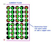
Thank you for the warning.
 
What nickel thickness are you doing? Hopefully, the SW2 can do .15mm nickel when new, but if it's been around a year or so, the internal LiPo battery gets too tired. I use a $25 welder with an RC Lipo drone battery.

It really shouldn't matter, but if the welder limits the building, I also go series with .15mm first, and switch to .10 mm for the parallel.


.
Fortunately or unfortunately for me I ordered .20mm, SW2 really struggles with this thickness. It did the first layer, but can't do the second.
 
The time has come to upgrade the bms. I bought a JBD BMS which has common port for charging/discharging. Existing BMS has separate C- and P- ports. I am not 100% sure, but can I connect the two wires the the common C- port of the JBD BMS?
 
If it's a common port BMS, then both the external charge connector negative and the external discharge connector negative connect together to the common charge/discharge port of the BMS.
 
I also have that same JBD BMS, but haven't put it into anything yet. Yes. The C- should take both the negative wires from the discharge plug and the charge plug. One of the review comments on the web page says it does a poor job of balancing, Guess I will find out soon.
 
Back
Top