How do I rebalance LiFePo4 Headway pack

bikeelectric

100 W
Joined
Mar 26, 2008
Messages
138
Location
Madison, Wisconsin
I have 16 cell Headway 10 ah pack that has been in use about 4 or 5 years and around 8000 or more miles on it. This winter I left it too long sitting and I guess the BMS drained it down to below 2v per cell. I was able to get it charged back up and seemed to work okay , until recently when battery charger failed. I checked pack and found some cells much lower than others so I replaced them with some spare cells.
Yesterday I was charging and heard a pop - and one of the cells I had replaced had gone to .5 volts so I guess that was what the pop was from. I replaced that cell and was charging and checked after awhile and that new cell was up to 4.2 volts so I quickly unplugged charger.
Should the BMS be protecting a single cell against going so high voltage ? Or should I discharge each cell to exact same voltage ( down to 2v ?) and then charge them all up together again ? I have Hobby King Accucell 6 charger to discharge or charge single cells .

Maybe it is time for a new battery pack since I have some mixed ages on the new and old cells.

Thanks for any advice
 
I would use your balance charger to charge each cell to 3.6 v is the simple answer.
Did you charge the new cell to match the old ones before you installed it ?
 
To start you need to give us a chart on the state of charge of your cells like.
1. 3.60v
2. 3.54v
3. 2.78v

16. 3.33v
This will help for the next step.
 
I like seeing a lifepo4 go 4 to 5 yr. 8,000 miles. That being said what are you running ? Type of motor and controller amp draw ?
 
This battery is on 9 continent motor that I go on special deal from Ebike kit . They sold them cheap because the wheel was not centered. The battery pack I got from a Joshua in Canada group buy. I pretty much abused the pack by letting it rattle around in back bike bag , get wet sometimes, etc . Only problem I had before was when connectors screws came loose or a few broken balance wires.

For some reason my Cycle Analyst reset erasing all the battery history other than I know how many miles - but would have been nice to be able to tell you how many recharges and amphour totals, etc but they are gone.

I think some of my problems started last year when my charger failed and I used cells may have gotten out of balance - plus before I figured out the charger had failed I put on a different BMS than original one and maybe that one didn't monitor each cell as well for balancing.

Here is the original write up I did on my bike .

http://endless-sphere.com/forums/viewtopic.php?f=4&t=9244

I think the Idea of single cell charge each cell up to the same level is a good idea and I will try that before I give up on the pack.
 
this does not make sense. if you have a BMS it is not always the reason the battery goes out of balance.

what BMS do you have and what did you do to test it to see if it was responsible for your battery having low capacity on some channels.

why did you replace the headway cans to begin with? what did you do to balance the pack to the new cans before installing them?

did you do a capacity test of the battery before removing the original cans? do you have a wattmeter?
 
Please start by writing down cell voltage before anything else. First. Then charge each cell to 3.6v. A set of sense wires and cellog like device with make this ez peze. 4~4s or 2~6s and a 4s.
 
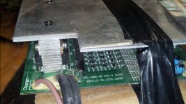
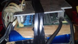
bms.jpgbms2.jpg
dnmun said:
this does not make sense. if you have a BMS it is not always the reason the battery goes out of balance.

what BMS do you have and what did you do to test it to see if it was responsible for your battery having low capacity on some channels.

why did you replace the headway cans to begin with? what did you do to balance the pack to the new cans before installing them?

did you do a capacity test of the battery before removing the original cans? do you have a wattmeter?

Yes looking back now I I see that what I probably did wrong was adding new cells without ensuring they were the same balance/ charge level as the others in the pack. I thought I had bad cell because the pack suddenly crashed - cut out by BMS I believe . I put a load on the pack and checked each cell and removed the ones that were much lower than the others since I thought they may be the ones causing the trouble.

I understand now that the way the BMS works is that it may not monitor each cell but rather when it sees the proper end voltage it will then allow the high cells to bleed off so the low cells can come up in voltage and balance - right ?

BMS says WL-086-01 FR-4 94VO
Rev 1.3 June 2008
photo attached

 
the charger will supply a balancing current when the pack has charged to the full voltage. this allows the cells with less than full charge to continue filling with charge as the BMS circuits shunt the current around the cells that are already fully charged.

if one cell goes to the HVC then the BMS will turn off the charging current to prevent that cell from overcharging since it cannot bypass enuff current to keep the cell voltage below the HVC.

then it will reset when the voltage on the highest cell drops enuff and it continues this process until enuff of the cells have climbed up in voltage to allow the charger to shift over to the CV mode where only the balancing current is pushed into the pack so it does not push to HVC anymore. this is where the balancing occurs.

we can show you how to test the BMS and also how to measure the capacity of the individual channels accurately.
 
dnmun said:
the charger will supply a balancing current when the pack has charged to the full voltage. this allows the cells with less than full charge to continue filling with charge as the BMS circuits shunt the current around the cells that are already fully charged.

if one cell goes to the HVC then the BMS will turn off the charging current to prevent that cell from overcharging since it cannot bypass enuff current to keep the cell voltage below the HVC.

then it will reset when the voltage on the highest cell drops enuff and it continues this process until enuff of the cells have climbed up in voltage to allow the charger to shift over to the CV mode where only the balancing current is pushed into the pack so it does not push to HVC anymore. this is where the balancing occurs.

we can show you how to test the BMS and also how to measure the capacity of the individual channels accurately.

Thanks - if you can point me to the info on how to measure to test BMS and measure capacity that would be great. From all the comments though I think I see problem was I put a cell that was too full in with some that were low so it probably didn't trigger HVC and then let too much current through the already full cell .

What current would you charge these 10ah cells individually ?
 
the headways can be charged at up to 1C but 1/2C is best imo.

it is usually easier to just use a power resistor with jumper wires with alligator clips to drain the excess charge off of the high cells and allow the charger to continue charging the pack up to full balance. most do not have the time or single cell charger to charge a battery up individual cells one by one.
 
You can also use a tail light bulb, solder some wires on and use to drain high cell ( cells ). This will help bms catch up. If you can use your rc charger as a single cell charger. The goal is 3.6 v or if 3.5v is easier. Then plug in charger with bms for a while. Balance.
 
All good advice - I am certainly learning a lot about Lithium battery packs now .
I have started to single cell charge each individually . No hurry since it has been rain anyway !
I was looking at battery internal resistance meters on ebay . Might be a good investment if I get a large battery pack from a friend that needs some major testing of cells.
 
Most gods would share. Can't figure out why this god always ask for gold. Why would a god need gold anyway ?
Data base ~ all you need for now is a voltage chart k.i.s.s. .
A true 4 wire I.R. would require to take battery apart and run a cycle test on each cell and ect.

Data Base.
1. 3.45v
2. 2.98v
3. Xxx

16. Xxx This is a good start.
I had a cheap I.R. tester I think it worked. I think I sent it to dnmun broken.
Docbass had a thread on it, can't find it. It did tell of cutting of the probes of two into one wire and putting two spring tips to on probe. Maybe some else has the link.
 
The Headway BMS activates the cell shunt resistor at 3.65 volts. On my unit that resistor is 20 ohms; 3.65/20 = 182 ma. If your charger is making that current or less then that cell stays at 3.65. If the charger taper is matched and the cells are not too far out of balance this will be the situation.

If the charger is putting out more current at that point then the cell voltage will be higher, e.g. 190 ma * 20 ohm = 3.8 volts. At 3.95 volts on any cell the BMS disconnects and probably the charger shuts off; after a few seconds of bleeding the BMS reconnects and the charger may start up again. So if a single cell is high it will get hammered while the others come up; worst case is a single cell low where the others will overvoltage. In either case the charger might not like the cycling (clicking noises bad!).

For severe imbalance charging or discharging individual cells is a good fast way to get back to the proper taper current for final balance, but if you have the time just insert a series resistor to limit the charger current to 150-160 ma. I use an analog meter and string of 1 ohm resistors with an alligator clip variable tap. Then individual cells will never go above 3.65 and the charger will not shut off until the cells are balanced. Of course if the imbalance is 5 amp-hours that will take 5/0.150 = 33 hours.
 
or instead of this contraption you can use the resistor drain the high cell down to the same voltage or lower than the others and then it will go into balance charge CV mode on the charger.

if you have a headway BMS you will have to verify that the balance voltage is 3.65V because they may have changed it to 3.60V now like all the other BMS stock format designs.

there is absolutely no reason to use a single cell charger or do anything weird. you have a cell that is high so just drain the excess charge off of it. do not charge up all the others by themselves one at a time.
 
god had spoken. E.S. is a place for Free learning and Free sharing. We don't charge. I use god with a small g for, if I could find a smaller g I would. Or leave out the g all together and add a d as odd.
There is a for section for profit, you can sale yourself there.
Now back to helping people.
Good luck with your pack as we can only tell the longevity of lifepo4 if work on older packs to find this 2,000 cycle mark. It may take new chargers and a bms on the way to this mark.
 
dnmun said:
or instead of this contraption you can use the resistor drain the high cell down to the same voltage or lower than the others and then it will go into balance charge CV mode on the charger.

if you have a headway BMS you will have to verify that the balance voltage is 3.65V because they may have changed it to 3.60V now like all the other BMS stock format designs.

there is absolutely no reason to use a single cell charger or do anything weird. you have a cell that is high so just drain the excess charge off of it. do not charge up all the others by themselves one at a time.

I already started single cell charging so will finish . How would I connect a resistor to drain one cell if I wanted to - from negative to positive across that one high cell ?
My Hobby King Accucell charger stop at 3.6v for the LiFe settings .It goes up to 3.6v and then decreases the current to maintain that voltage but so far has timed out at 2 hours before its logic would say full.

I have another walwart looking single cell charger that says it goes to 3.65v .

So I will finish charging each cell individually and then make record of resting voltage of each cell.
On a related note - I bought the $30 special ebay Lithium charger
http://www.ebay.com/itm/331352893958?_trksid=p2057872.m2749.l2649&ssPageName=STRK%3AMEBIDX%3AIT
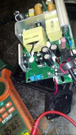
which says 48v but there are two pots inside. I can turn one of them with no connections to get voltage up to 57.69 . Does anyone have any idea what the two pots would set - for example perhaps the one I turned is the charger ending voltage - what would the second pot adjust ?
see photo of charger
 

Attachments

  • new charger.jpg
    new charger.jpg
    212.2 KB · Views: 3,261
Check charger voltage 16s should be 58.4
So 48v lipo4 can be lower. 14s ~53.4v or so.
You can put a short straw on the charger prongs when testing so as not to short that MM probes in the housing. Report back.
 
999zip999 said:
Check charger voltage 16s should be 58.4
So 48v lipo4 can be lower. 14s ~53.4v or so.
You can put a short straw on the charger prongs when testing so as not to short that MM probes in the housing. Report back.

Yes I know I took gamble getting this charger that it may not be the right one for LiFePo4 type batteries. But am hoping it is possible to tweak it . But voltage I turned it up to divided by 16 equals 3.6v per cell though perhaps not enough voltage to make up for loss in BMS and elsewhere.
 
dak664 said:
The Headway BMS activates the cell shunt resistor at 3.65 volts. On my unit that resistor is 20 ohms; 3.65/20 = 182 ma. If your charger is making that current or less then that cell stays at 3.65. If the charger taper is matched and the cells are not too far out of balance this will be the situation.

If the charger is putting out more current at that point then the cell voltage will be higher, e.g. 190 ma * 20 ohm = 3.8 volts. At 3.95 volts on any cell the BMS disconnects and probably the charger shuts off; after a few seconds of bleeding the BMS reconnects and the charger may start up again. So if a single cell is high it will get hammered while the others come up; worst case is a single cell low where the others will overvoltage. In either case the charger might not like the cycling (clicking noises bad!).

For severe imbalance charging or discharging individual cells is a good fast way to get back to the proper taper current for final balance, but if you have the time just insert a series resistor to limit the charger current to 150-160 ma. I use an analog meter and string of 1 ohm resistors with an alligator clip variable tap. Then individual cells will never go above 3.65 and the charger will not shut off until the cells are balanced. Of course if the imbalance is 5 amp-hours that will take 5/0.150 = 33 hours.

Okay -I was wondering how that BMS is supposed to work. Makes sense. But as someone said - all depends on which BMS you have as to how much it would protect a cell way out of balance from the others. In my case charger was well below final voltage and it let one cell go way above 4.2 v until it got ruined.
 
Now look what I got myself into - picked up a long neglected Headway pack from a friend and will have to figure out if any or all of these cells are good. The pack was shipped wrapped in this weird red crumbly type thin board - looks like it could be asbestos !
 

Attachments

  • asbestos.jpg
    asbestos.jpg
    50.4 KB · Views: 2,634
I have around 7000 miles on my headway 36v 15ah pack. It gets me around town at about 85% of what it used to do. 17 miles before LVC as apposed to 20 miles when it was new. Headway cells are robust IMO.

If you are charging individually then, I think you should also take the time do do a capacity test individually.

Here is the long way to go to understand your cell conditions:

Use a permanent marker and number each cell.

Charge each cell, with your Accucell charger to 3.6v and then discharge them to 2.5v. Keeps notes on the time it took to reach 3.6v and the time it took to discharge to 2.5v. Also note the capacity of each cell. This is very important!

Once all your cells are at 2.5v then reassemble the pack and charge with your bms attached. Check the voltages of every cell, at 30 minute intervals while charging. Note which cells are charging faster and slower.

List your notes here on ES.

On the charger one of those pots should be for output voltage and the other for either current (amps) or changing from constant current to constant voltage (CC to CV).

The 57.69 on the charger is (57.69/16=) 3.605625v per cell. Nothing wrong with that voltage. I undercharge my headway cells by about .5v all the time. 3.60v per cell. I wouldn't bother to change the pots

If you put a power-meter inline, between the battery pack and the charger you will note the changes in volts and amps as you adjust the pots. BE VERY CAREFUL NOT TO GO WILD ON THE ADJUSTMENTS UNTIL YOU ARE SURE WHICH ONE DOES WHAT.

You can also test the voltage and current with you dmm. Check the voltages on the output wires where they are soldered to the pc board, or at the connector between the battery and the charger, while charging under load. Check the current by changing the DMM to test at 10amps and connecting the probes inline with your negative wiring to the battery.

I think a inexpensive power meter is the easier way to go.

God luck :lol:
 
What do you mean by power meter - one that reads watts ? I have to read up on my accucel charger to see if I can change default timeout - because it will timeout at 2 hours of charging and it will be at 3.6v . Do you know how it determines end of charge ? My Acucel charger only discharges 1 amp so will take a long time to drop down to 2.5v .

Good advice e-beach
Yes I should keep some records and will do that for this pack I just got that needs some TLC.
 
Back
Top