How do I rebalance LiFePo4 Headway pack

bikeelectric said:
What do you mean by power meter - one that reads watts ? I have to read up on my accucel charger to see if I can change default timeout - because it will timeout at 2 hours of charging and it will be at 3.6v . Do you know how it determines end of charge ? My Acucel charger only discharges 1 amp so will take a long time to drop down to 2.5v .

Good advice e-beach
Yes I should keep some records and will do that for this pack I just got that needs some TLC.

Power meters like these:

http://www.ebay.com/itm/Boat-RC-Wat...6&pid=100005&rk=1&rkt=6&sd=191234570524&rt=nc

http://www.ebay.com/itm/New-GT-Powe...524?pt=LH_DefaultDomain_2&hash=item2c8677f91c

As for the time it takes your accucel charger to discharge the cells, yes a long time, but you really need to group the cells that have largest capacities together or the bms will cut off the pack because one of the cells reaches lvc much earlier then the others. With the capacities all known, then you can group the ones with the highest capacities together and have a pack that will last as long as possible with the cells you have.

If you have a power meter then you can use a capacity drain setup to drain the cells at a quicker pace and still get the same information. Weather it is big resistors or light bulbs or dc motors or what every you want to use to drain the cell. If you are diligent and watching carefully then you can get all the info you need from a power meter.

Beware, a power meter will not stop the process like your accucel charger. You have to be there watching the process!!!

Look at you accucel manual to see how you can adjust it to best suit your needs for your Headways.

:D
 
For a little over ten bucks I ordered one of those meters. And yes, I will need to set up a proper test station to gather data on those cells. I would think you could automate the shut off with simple arduino program and relay.


bikeelectric said:
For a little over ten bucks I ordered one of those meters. And yes, I will need to set up a proper test station to gather data on those cells. I would think you could automate the shut off with simple arduino program and relay.

I have never taken the time to learn arduino, but I am sure somebody has figured a way to cut off a discharge at a prescribed voltage.

Since Headways can sustain a 2C continuous discharge a 20amp discharge station could work.

If my math is wrong somebody please correct me but it could go like this....(depending on the Ah of the cells)

10ah x 2C = 20ah x 3.6v = 72 watt hours / 60 watt incandescent light bulb = 1 hour and 12 minutes for discharge or maybe a little bit longer then 72 minutes per cell.

Some minor experimentation will be necessary. Check your local lighting or auto parts store for something that will work.

http://www.elightbulbs.com/Eiko-480...oogleBaseCSE?gclid=CLrZmIGZ7cQCFREoaQodiLEACw

:D
 
Okay - just found an instructable where he made one with voltage alarm monitor - took the buzzer off and ran it into latching relay to turn off discharge. Pretty simple and inexpensive circuit.
http://www.instructables.com/id/Make-a-Battery-Protection-Circuit-low-voltage-cut-/

http://www.ebay.com/itm/1-8S-Lipo-Li-ion-Fe-Battery-Voltage-2IN1-Tester-Low-Voltage-Buzzer-Alarm-DX-/261666670811?pt=LH_DefaultDomain_0&hash=item3cec8c88db
 
One your calculation above you would need to find a 3.6v 60 watt light bulb to do that .
Or if you could find power resistor rated for 60 watts
+ 20.00 amps
/ 3.60 volts
---------------
+ 5.56 ohms

Right ?

http://www.ebay.com/itm/4-x-50W-6ohm-Load-Resistors-For-Hyper-Flash-Turn-Signal-Blink-Blinker-LED-Bulb-/251810642517?hash=item3aa1157a55&vxp=mtr
 
i use the oil filled electric radiator type heaters. you have to not use the switch on the heaters or allow the thermostat on the oil filled heater to cycle on and off since they are on DC current and the switches will burn out.

i used to have a picture of a regular duplex outlet i had wired up with anderson connectors and i would plug in up to 6 heaters at a time.
 
.18 Ω I believe?, .......but it must also take the current (watts).

Easier I think to go to the auto parts store and get a $3.00 12v headlight bulb and use it as a resistor. If you get a halogen bulb then you can hook it up with alligator (crocodile) clips.

:D
 
Personally I used a single cell LiFePO4 charger to initially balance my 16S/10Ah headway pack. Similar to this one on ebay, except mine came with aligator clips. It's not as fast as some of the (also good) methods mentioned here but it's certainly simple. If this were my pack, I would charge each cell individually to 3.65V, then run the pack down and watch each cell. Weak ones should hit 2.5V while the rest are still above 3.0V or so.

8000 miles isn't that much for a headway pack unless some cells are damaged. Assuming 20 miles per cycle (just a guess) that's only about 400 cycles.

I see you're in Madison, so if you want to borrow my single cell charger sometime let me know. I'm also looking to buy some more headway cells relatively soon so if you want to do an order together and split shipping I might be interested.
 
dmwahl said:
Personally I used a single cell LiFePO4 charger to initially balance my 16S/10Ah headway pack. Similar to this one on ebay, except mine came with aligator clips. It's not as fast as some of the (also good) methods mentioned here but it's certainly simple. If this were my pack, I would charge each cell individually to 3.65V, then run the pack down and watch each cell. Weak ones should hit 2.5V while the rest are still above 3.0V or so.

8000 miles isn't that much for a headway pack unless some cells are damaged. Assuming 20 miles per cycle (just a guess) that's only about 400 cycles.

I see you're in Madison, so if you want to borrow my single cell charger sometime let me know. I'm also looking to buy some more headway cells relatively soon so if you want to do an order together and split shipping I might be interested.

Thanks for the offer of charger loan David - I have one of those with alligator clips. Yes good idea on filling up and discharging the pack - I did something like that at first to find bad cells though I hadn't ensured that all cells were full and balanced. I was using 300 watt halogen light as load .
 
It's all fun but be careful as there is a lot potential energy stored. They can cause a fire. I have a steel can if they reverse polarity or short somehow.
I you mean it's good to have an escape plan just in case. I have a can I can throw then in and take outside or something to get them out of the garage etc
Things happen.
 
I have four chargers like that at 2a and put them together for faster charge. I think they must be isolated or something to work on parallel. Their voltpheaks With I could find them.
 
Kiriakos GR said:
dmwahl said:
Assuming 20 miles per cycle (just a guess) that's only about 400 cycles.

My HW-RH05/ 38120 cells did 50Km average at winter time and start of spring does 60Km, and I am expecting 75km per charge start of July.
I get about 25 miles (40km) out of my 16S/10Ah headway pack at 80% DOD, so I was being conservative in my guess. More miles per charge will only mean fewer cycles or less discharge per cycle. Either way those cells should easily go 20,000 miles or more if treated well.
 
After single cell charging this weekend, I made my 4.5 mile commute in this morning - took it kind of slow so didn't go over 20mph and the voltage held up very well all the way in.
I checked all cell voltages after that and they are close enough , and also put a 150 watt load on the pack and checked voltages and they were close. Now I am charging with the charger cranked up to max voltage ( left pot ) and turned the current down to 2.4 amps ( right pot ) . I will keep a watch on cell voltages .

The only thing I wonder about - the original charger used to go full charge, but near the end it would run the fan off but LED indicator would still be charging at lower current - which I figured is when BMS was balancing. This charger from what I could tell yesterday seems to cut out at the voltage that the left pot was set at which is 57.7v max that I could turn it up to.
 
bikeelectric said:
......I checked all cell voltages after that and they are close enough , ......

What is close enough? Did you check the cells for capacity and use the best ones?

:D
 
e-beach said:
bikeelectric said:
......I checked all cell voltages after that and they are close enough , ......

What is close enough? Did you check the cells for capacity and use the best ones?

:D

I have not had the time to do capacity check on all the cells. They did seem to be going a few tenths of a volt different from each other when they got to the end of the charge - when the charger kicks off. Until I get the new 16s LifePo4 charger that I just ordered I am hoping to be able to use this charger . I don't think the charger I am using now is cutting out to a low enough current at the end to let the BMS properly balance the cells - plus it probably does not get quite high enough in voltage to let the balancing of the BMS turn on ?

So without destroying my cells I am hoping to get by until I get proper equipment and time to evaluate the cells one by one and document the details.
 
dak664 said:
The Headway BMS activates the cell shunt resistor at 3.65 volts. On my unit that resistor is 20 ohms; 3.65/20 = 182 ma. If your charger is making that current or less then that cell stays at 3.65. If the charger taper is matched and the cells are not too far out of balance this will be the situation.

If the charger is putting out more current at that point then the cell voltage will be higher, e.g. 190 ma * 20 ohm = 3.8 volts. At 3.95 volts on any cell the BMS disconnects and probably the charger shuts off; after a few seconds of bleeding the BMS reconnects and the charger may start up again. So if a single cell is high it will get hammered while the others come up; worst case is a single cell low where the others will overvoltage. In either case the charger might not like the cycling (clicking noises bad!).

For severe imbalance charging or discharging individual cells is a good fast way to get back to the proper taper current for final balance, but if you have the time just insert a series resistor to limit the charger current to 150-160 ma. I use an analog meter and string of 1 ohm resistors with an alligator clip variable tap. Then individual cells will never go above 3.65 and the charger will not shut off until the cells are balanced. Of course if the imbalance is 5 amp-hours that will take 5/0.150 = 33 hours.

I was just reading this again for better understanding. I guess my charger would be difficult lower the current to let BMS do this since it does not seem to have the low current mode - only off at certain voltage. I guess I will have to clip some resistors or light bulb on any high cells for now to get by. New charger is on order.
 
bikeelectric said:
I was just reading this again for better understanding. I guess my charger would be difficult lower the current to let BMS do this since it does not seem to have the low current mode - only off at certain voltage. I guess I will have to clip some resistors or light bulb on any high cells for now to get by. New charger is on order.

Ok, maybe I missed something here...do you know for sure that the bms you have needs 3.65v for the bms to work? Or is it just a guess?

Also, on your charger, it might stop at the terminal voltage only to activate once the bms drains one or two of the higher cells. If you monitor the cells as they charge you could see if the charger and bms are working properly.

You are at a point where you should not get sloppy with your battery pack for a while.

The more fastidious you are with your testing and note taking for the next few weeks the better off you will be in the long run.

If you want to get a little sloppy later that will be fine, but now is the time to be a stickler for details.

:D
 
no, he means organizing your thoughts so you know what you are doing so your efforts are not totally wasted like this. but you gotta feel sorry for the guy when so many weird ideas are just dumped on him and he has absolutely no idea about how the BMS works are even what the balance voltage is or how the charger pushes charge. there is so much misinformation for newbies to plow through and no real accurate advice about batteries except how to go fast on your ebike.
 
dnmun said:
no, he means organizing your thoughts so you know what you are doing so your efforts are not totally wasted like this. but you gotta feel sorry for the guy when so many weird ideas are just dumped on him and he has absolutely no idea about how the BMS works are even what the balance voltage is or how the charger pushes charge. there is so much misinformation for newbies to plow through and no real accurate advice about batteries except how to go fast on your ebike.

Thanks to everyone here I am putting all the pieces together. I have been studying up on ebikes for 10 years and riding one the last 5 or 6. Guess I was spoiled because the first battery and charger I got worked just great despite no careful monitoring.

But now that I am closely watching how each cell individually reacts to discharging and charging along with all the experiences of others , I am seeing this in real life. Hands on along with the book learning is the best way to really understand. It takes some close observation - and yes I am writing down notes for each cell now too.

I have watched some technical talks from chemists about different lithium batteries , and while I understand what they said, I would be hard pressed to try and explain in technical detail to someone else what they said. I do appreciate everyone helping me dig into my battery pack step by step . Your time is not being wasted .
 
e-beach said:
bikeelectric said:
I was just reading this again for better understanding. I guess my charger would be difficult lower the current to let BMS do this since it does not seem to have the low current mode - only off at certain voltage. I guess I will have to clip some resistors or light bulb on any high cells for now to get by. New charger is on order.

Ok, maybe I missed something here...do you know for sure that the bms you have needs 3.65v for the bms to work? Or is it just a guess?

Also, on your charger, it might stop at the terminal voltage only to activate once the bms drains one or two of the higher cells. If you monitor the cells as they charge you could see if the charger and bms are working properly.

You are at a point where you should not get sloppy with your battery pack for a while.

The more fastidious you are with your testing and note taking for the next few weeks the better off you will be in the long run.

If you want to get a little sloppy later that will be fine, but now is the time to be a stickler for details.

:D
No I am not sure that my BMS needs 3.6v . I felt the resistors when my charger cut off and some of them were quite warm so must have been doing something.
From what I can tell my charger latches off when it hits limit voltage. It will not start up again and charge until you unplug it and repower. My guess is that a different charger will do what you say - hang around monitoring and come on and off and lower it's current at the top of voltage. That is what my original charger did. And that is what is described in the charger I ordered yesterday.

I have removed my battery pack this morning again after commuting in and while charging am monitoring each cell voltage and making notes. I wish there was not a big piece of aluminum heat sink in the way of the balance resistors , otherwise I could use thermal imaging gun to try and see if it can see which resistor is on and see if it correlates with the higher voltage cells I am noting. I may install the older BMS I have since it does not have this aluminum heat sink in the way so I can do that.
 
you can tell if the BMS is functional by testing it directly.

to determine of the shunt transistor is turned on then measure the voltage across the shunt resistor to determine how much current is flowing through the shunt transistor.

the BMS manufacturer will have the balancing voltage listed in their data sheet.
 
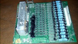
bms.jpg
dnmun said:
you can tell if the BMS is functional by testing it directly.

to determine of the shunt transistor is turned on then measure the voltage across the shunt resistor to determine how much current is flowing through the shunt transistor.

the BMS manufacturer will have the balancing voltage listed in their data sheet.

Do you know the manufacturer of the BMS in photo or where I would find the specs for it ? It came with Headway battery pack in group purchase.
 
that is the original BMS that headway used on their packs. it seems to be missing a lot of mosfets. that may have the 3.65V balancing voltage because they are about 8 years old now. but it is easy to determine when you finally charge the battery up and can measure them.
 
dnmun said:
that is the original BMS that headway used on their packs. it seems to be missing a lot of mosfets. that may have the 3.65V balancing voltage because they are about 8 years old now. but it is easy to determine when you finally charge the battery up and can measure them.

I put that BMS back on and some of the balancing resistors do turn on. I can see the ones that are heating up with the thermal imaging Flir gun. But not too long after they turn on the charger will shut off . Some of my cells do go a lot higher than the others and it is the ones that I had added and are not from the original batch. So until I get my new charger there will not be enough time for them to balance with the BMS, but with my current charger cutting from what I can tell it does not get high enough voltage to damage any of the high cells.

I also tried putting large 10 ohm resistor in line with charger to lower current = which it did but charger still cuts off too early so that does me no good either.
 
Back
Top