MacGuyver_Season1
100 mW
Luna got back to me and said their BBSHDs come with the better mosfets and rotor now, so I went ahead and ordered a new “bare bones” motor/controller. Will report back progress. Thanks everyone.


Also, FYI tested it on bike stand. Would run wide open for 20 minutes (or more) under no load with zero rise in temps of case (controller or stator side). I obviously bogged it down in too high of a gear under load to fry windings like that. So it can handle the current, just not heat/stress/low rpm. Argh, back to drawing board…Well, very surprised by that. Thought battery would be weakest link, not core. Did that with original nylon gear as well, which I thought would be somewhat of a buffer. Lessons learned I guess. Looking at heat sinks, fish tank temp probes, potentially a larger/wide-range cassette. But….it was awesome for about 10 minutes.
Well, very surprised by that. Thought battery would be weakest link, not core. Did that with original nylon gear as well, which I thought would be somewhat of a buffer. Lessons learned I guess. Looking at heat sinks, fish tank temp probes, potentially a larger/wide-range cassette. But….it was awesome for about 10 minutes.
No load is just that--no load.Also, FYI tested it on bike stand. Would run wide open for 20 minutes (or more) under no load with zero rise in temps of case (controller or stator side). I obviously bogged it down in too high of a gear under load to fry windings like that. So it can handle the current, just not heat/stress/low rpm. Argh, back to drawing board…
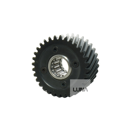
No it’s actually version B. I have an original version A too. I‘ve actually since swapped out version A windings into version B motor housing and reinstalled version B rotor (so bottom bearing size matches and still maintain strength of version B rotor). Working with no error codes so far, but want to put more thermal/current/load protection in place before I just go out and burn windings again. Looking at heat sinks, etc. Wondering if cpu thermal paste could be applied between rotor and coils? That seems to be where a ton of friction and heat is generated.That looks like the ver.A rotor. Square cut gear right up to the laminations. I would say replace the whole motor assy. with the ver. B model. The shaft will be on the list of things to break if you don't. I broke mine at stock 1500W doing wheels up launched testing a chain guide. You need the better one anyway.
*Technically not “Version A” with the Anderson phase connectors, but the older B version with the rotor which still had the issue of breaking. Circa mid-2016.No it’s actually version B. I have an original version A too. I‘ve actually since swapped out version A windings into version B motor housing and reinstalled version B rotor (so bottom bearing size matches and still maintain strength of version B rotor). Working with no error codes so far, but want to put more thermal/current/load protection in place before I just go out a burn windings again. Looking at heat sinks, etc. Wondering if cpu thermal paste could be applied between rotor and coils? That seems to be where a ton of friction and heat is generated.
Hmm, interesting. Will look out for that, thanks.Just make sure you get a full password/etc for using the setup software (BACdoor?).
Unless things at ASI have changed, if you don't get your own personal "forever" password from ASI, you may not be able to change any settings to tune things, correct problems, etc. People have had issues with some dealers giving them the deaier password, then ASI turns it off and they're stuck with a controller they cannot change settings on anymore.
I've put CPU paste between the coils and the cover to get a wet joint there. Putting paste between the rotor and coils won't work because it's moving. There is a ferrro fluid mod that's done on hub motors that put oil with metal in it onto the magnets on the outside, to cool the rotor on the inside. But because of the higher motor speed the friction loss and heat gain is too much on mid drives. Luna has the stronger PEEK plastic gears in stock again.No it’s actually version B. I have an original version A too. I‘ve actually since swapped out version A windings into version B motor housing and reinstalled version B rotor (so bottom bearing size matches and still maintain strength of version B rotor). Working with no error codes so far, but want to put more thermal/current/load protection in place before I just go out and burn windings again. Looking at heat sinks, etc. Wondering if cpu thermal paste could be applied between rotor and coils? That seems to be where a ton of friction and heat is generated.
 lunacycle.com
 ebikes.ca
Looks like mine. The magnets actually came loose and flung off the rotor!Well, very surprised by that. Thought battery would be weakest link, not core. Did that with original nylon gear as well, which I thought would be somewhat of a buffer. Lessons learned I guess. Looking at heat sinks, fish tank temp probes, potentially a larger/wide-range cassette. But….it was awesome for about 10 minutes.
How is that possible for an IPM rotor? Other people should have also reported this by now then.Looks like mine. The magnets actually came loose and flung off the rotor!
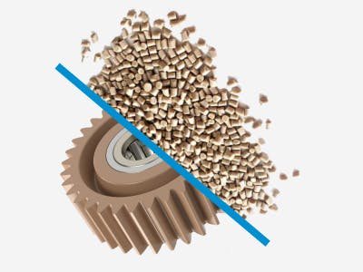
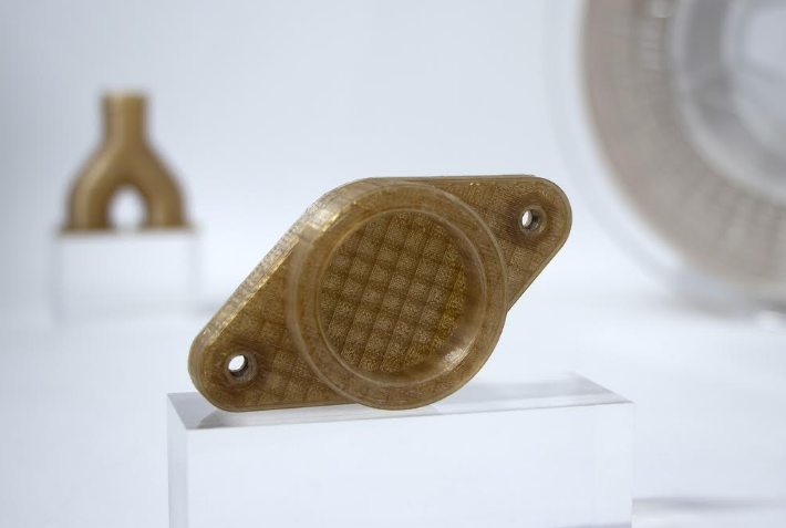
What are peek gears actually made of? It just says it has some carbon mixed in , are they plastic or something else. Like some kind of heat resistant aramid or something? Or ceramic?
 industrial.vestakeep.com
 3dprint.com