How-To: GT2B --> Badwolf v2

cdn said:
jamesonotc said:
cdn said:
Great write up. Now can proceed to do the same. Only thing missing is to print the enclosure. Where did you get it printed? Hopefully some place local because I'm in Renton.

Good to see you another local,I too am in Renton

I'm currently building a board and will be using a case I got from sl33py for my gt2b swap, lets link up sometime!

how far are you along with your project on the other portion of your build?

Sounds like a plan. I'm pretty close to final assembly. This build is a revamp of an existing running board. Just waiting for bearings.

cdn - i have some spare bearings coming out my ears... All yours if you want to meetup since you are local? Shoot me a PM.
 
sl33py said:
Yeah, desoldering the USB charging port is a PITA. I still haven't found my desolder wick, so i will either grab some at Fry's or just do what i did with the first one again (grind off the sides and lever it off w/ heat).

Try using some braided wire dipped in flux. Here's a "how to" on the subject. http://www.dynatron.org/howto/XBOX/hackit/wick.html
 
chaka said:
sl33py said:
Yeah, desoldering the USB charging port is a PITA. I still haven't found my desolder wick, so i will either grab some at Fry's or just do what i did with the first one again (grind off the sides and lever it off w/ heat).

Try using some braided wire dipped in flux. Here's a "how to" on the subject. http://www.dynatron.org/howto/XBOX/hackit/wick.html

Thanks Chaka - that actually the first thing i tried. It helped a little, but it was easier to just mangle it off w/ brute force.

Looking at your link i might try it again w/ the smaller set of wires from the larger like he shows. likely more successful. Thanks man!
 
sl33py said:
cdn said:
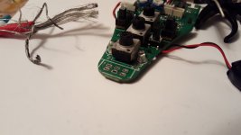
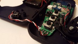
View attachment 1View attachment 2Just got finished the swap. Once again sl33py's write up with pix was invaluable.

The hardest part of the swap was the unsoldering of the usb port and the correct placement positioning of the trigger assembly. I think the most time was spent making the trigger assembly fit properly without having to modify the case.

Nice work cdn! I am working on v2 next w/ my other GT2B's. I was going to do what you did w/ the resistors on the next one - use the wires on the steering wheel connector/plug to solder the resistors to. I'll try to take a pic or two when i do this w/ the next one.

Yeah, desoldering the USB charging port is a PITA. I still haven't found my desolder wick, so i will either grab some at Fry's or just do what i did with the first one again (grind off the sides and lever it off w/ heat).

So you have full range on the trigger w/o removing any of the plastic like i did? I'm just wondering if the opening is too small, or if my first print was low quality and not 100% correct dimensions for that opening. I broke down and ordered the 2 sets from Shapeways (spendy), because i want to compare quality w/ the first one. Also ships right to my door vs trying to coordinate w/ someone on 3dhubs. $5 shipping well spent.

Where did you get your print specifically - looks good! If 3dhubs i'll try to use that location!

Looking at your pix, it looks like your trigger assembly is positioned in the same spot as mine. Before disassembly of the trigger assembly from the GT2B, I placed a mark with a silver Sharpie on the arm where full throttle would stop and also where braking would stop. When positioning the trigger assembly in the new case, you can use the marks you made to make sure you have full throttle and braking before you tighten the nut down. When using the lever for braking there's not that much movement needed as compared with the throttle. When throttling my trigger just clears the case. By leaving the trimmed control plate in place, it served as my throttle stop. No modification to the case was needed for correct trigger movement.
I had mine printed at a UPS store in north Seattle. I'm embarrassed to say how much I paid to have this thing printed when you mentioned the cost at Shapeways for $35. I paid more than double that.
Overall the 3d printing quality was alright. I was expecting something that was a little thicker in material. The case seems to flimsy. I'll have to inquire if they can change the thickness for my next 3d print. I don't think I will use UPS again because of price. He did mention if I had a bulk order that he'd give me a discount. I'm wanting 3 more printed up and I don't think that qualifies as a bulk order.
 
cdn - i have some spare bearings coming out my ears... All yours if you want to meetup since you are local? Shoot me a PM.[/quote]
Hey sl33py. Thanks for the offer but my bearings came in today. Just finished assembly tonight. Testing tomorrow :D .
 
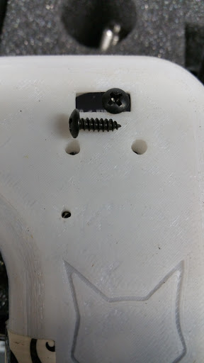
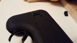
I was fiddling in the garage today and decided i'd try to fix the power switch not lining up. Looking down into my badwolf v2 case - the power switch pretty much lines up perfectly w/ the on/off opening. Again - not sure if it's a low-quality print issue or what, but the offset switch i printed didn't work since my switch isn't offset at all...

So - i drilled a small hole in the existing switch (1/16 i think was my smallest drill bit), and then screwed a small button head screw into it securely. Works perfectly and the button head is smooth which is nice.

It will complicate taking the case apart, but i do that infrequently so not worried about it. I can router out the hole to clear the button head, or possibly dremel the button head flat top/bottom for it to slide/clear if needed.

I updated the first post with this fix, but here it is as well w/ my longer description.
20150829_172120.jpg
 
chaka said:
You dont seem to need to cut the pcb on the badwolfv2. Is there another reason why people are cutting the board? It seems to fit perfectly uncut.


I will try this aswell. I really don't want to be cutting the pcb. I have some silver thing under the cutting area and I have a flysky gt2b so if anyone else knows what that silver thing is please tell me.
 
chaka said:
You dont seem to need to cut the pcb on the badwolfv2. Is there another reason why people are cutting the board? It seems to fit perfectly uncut.


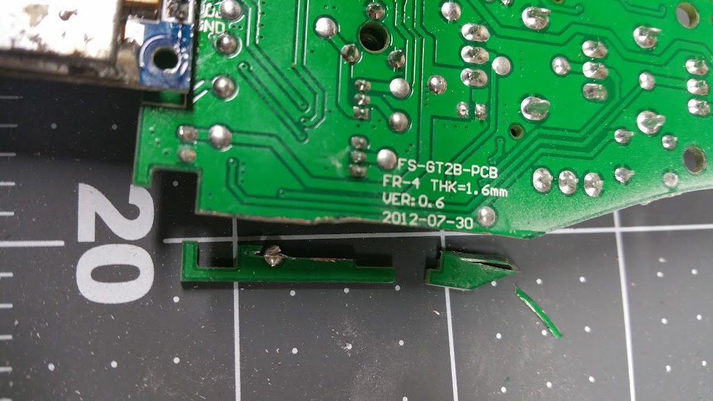
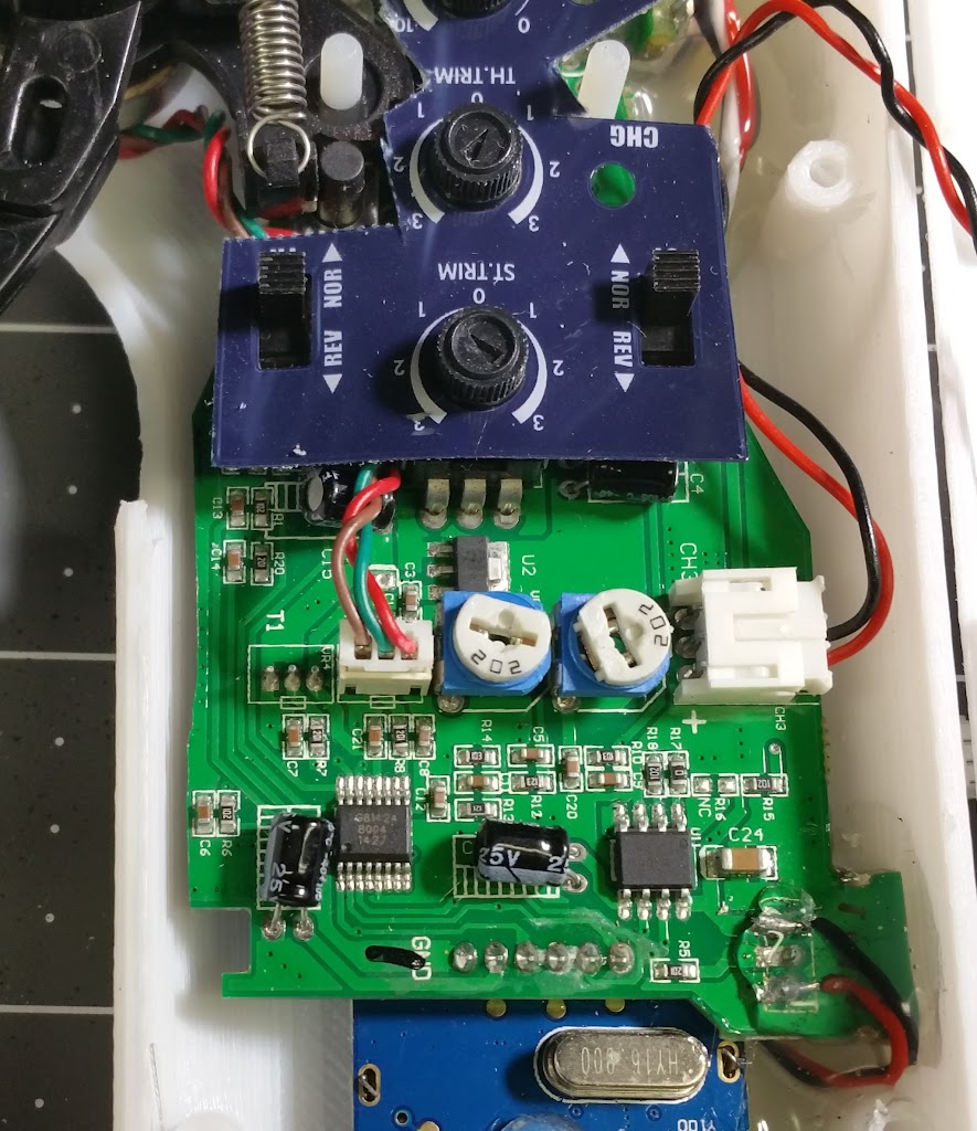
Thanks chaka. Odd. I looked back and on mine it definitely would not fit without cutting the pcb:
20150815_154122.jpg


Not sure if this is just another thing showing the lower quality print i got? Perhaps it shrunk more than yours? Just not sure. I will definitely compare when i get the others from Shapeways in a few days and let you all know.

As for the "silver thing" - it's no biggie - you can see in my pics where i cut through it. No adverse affect. Obviously if it fits without - why mess with it, but if it doesn't fit i wouldn't worry about cutting through it.

GL!
 
lox897 said:
chaka said:
You dont seem to need to cut the pcb on the badwolfv2. Is there another reason why people are cutting the board? It seems to fit perfectly uncut.


I will try this aswell. I really don't want to be cutting the pcb. I have some silver thing under the cutting area and I have a flysky gt2b so if anyone else knows what that silver thing is please tell me.

I'm pretty sure the PCB is the same for both HK and FS GT2B's - if you look you can see the "model #" on this HK pcb. Also the silver thing i cut through:
20150815_155711.jpg
 
Looks good chaka!

Question on your switch. I got some similar ones when i planned to redo mine since it didn't line up for the extension, but the small switches i got are only two prongs, not 3. ??? Can i share the middle contact on the PCB to each leg on the SP switch? That make sense?

Definitely going to try the solder wick trick like you did there. I have some desolder wick somewhere (lost), but have tons of wire kicking around to try this. I have two more GT2B's to convert - just waiting on the 3d prints to show up now.

One other "tip" i'll update the first post - reinforce the screw holes. 3d prints (at least the ones i currently have) seem flimsy and not well supported (i snapped two bottom ones off), so i'm going to give each a good "glob" of hot glue around them to reinforce them to the rest of the case. Can't hurt (besides hot glue string mess), and hope it will make those more durable for the infrequent need to crack it open and not worry about breaking them off.
 
sl33py said:
lox897 said:
chaka said:
You dont seem to need to cut the pcb on the badwolfv2. Is there another reason why people are cutting the board? It seems to fit perfectly uncut.


I will try this aswell. I really don't want to be cutting the pcb. I have some silver thing under the cutting area and I have a flysky gt2b so if anyone else knows what that silver thing is please tell me.

I'm pretty sure the PCB is the same for both HK and FS GT2B's - if you look you can see the "model #" on this HK pcb. Also the silver thing i cut through:
20150815_155711.jpg

Thanks sl33py.
 
sl33py said:
chaka said:
I'm having trouble with the switch extension too. This little spdt switch should do nicely.


Looking all over and can find 2 pin SPST micro switches easily... 3 pin SPST (What you have here correct - there is no "middle" just on/off SPST) are elusive at this size.

If you follow that link I left you it will take you to a spdt mini rocker switch. Its a 3 pin on off switch.
 
I bought mine from shapeways and has just been dispatched from NY so hopefully will arrive in Australia soon. My family is going on a holiday to america soon. Do you guys live near San Fransico, New York or anywhere else? Maybe we could meet up?
 
Mine lines up with the shapeways print. Except Usb of course. How do you screw in? Mine doesn't have threads and it just plops in. Am I missing something?
 
chaka said:
If you follow that link I left you it will take you to a spdt mini rocker switch. Its a 3 pin on off switch.

The link you sent me is a slightly larger switch, so i'm sticking with the screw on my white case.

I think i've figured out the switch lining up issue. It seems to depend on the angle of the PCB. So with a single plastic nut/riser (from the standoff kit i have) it sits lower and the radio at the bottom touching the case bottom has the switch angled more towards the bottom - which then doesn't line up with the extra printed offset extension. If you elevate the bottom radio slightly to keep the PCB more flat/level - the printed extension seems to lineup.


lox897 said:
Mine lines up with the shapeways print. Except Usb of course. How do you screw in? Mine doesn't have threads and it just plops in. Am I missing something?
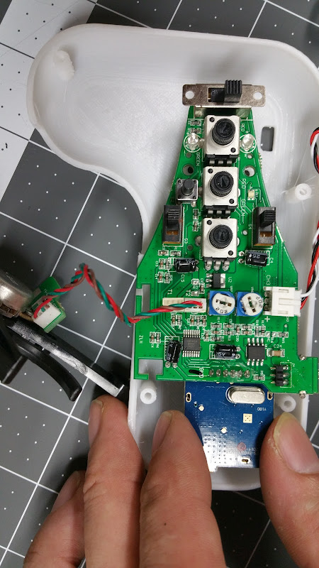
20150815_201031.jpg


Lox - you need hot glue to secure the moved USB charging port. You can mostly see it in the picture above. No screws. Nothing to screw to, unless you printed some sort of clamp and base for the USB port. Easier to just use hot glue. If you have a dual temp hot glue gun, use low if you can - on high it can warp/melt your 3d printed enclosure so be careful.
 
Thanks sl33py but I was talking about connecting the top and bottom of the actual case together.
 
lox897 said:
Mine lines up with the shapeways print. Except Usb of course. How do you screw in? Mine doesn't have threads and it just plops in. Am I missing something?

I haven't done any prints with Shapeways previously but it sounds like their tolerance are different compared to standard FDM/FFF printing. There are no threads in the model, instead it's the hole is slightly smaller then the screw so the screw creates the threads in the plastic when you first screw it together.
 
What screw did you use? I am using the one that holds the original casing together.
 
Back
Top