how to program a sevcon gen4

@66sametk@gmail.com
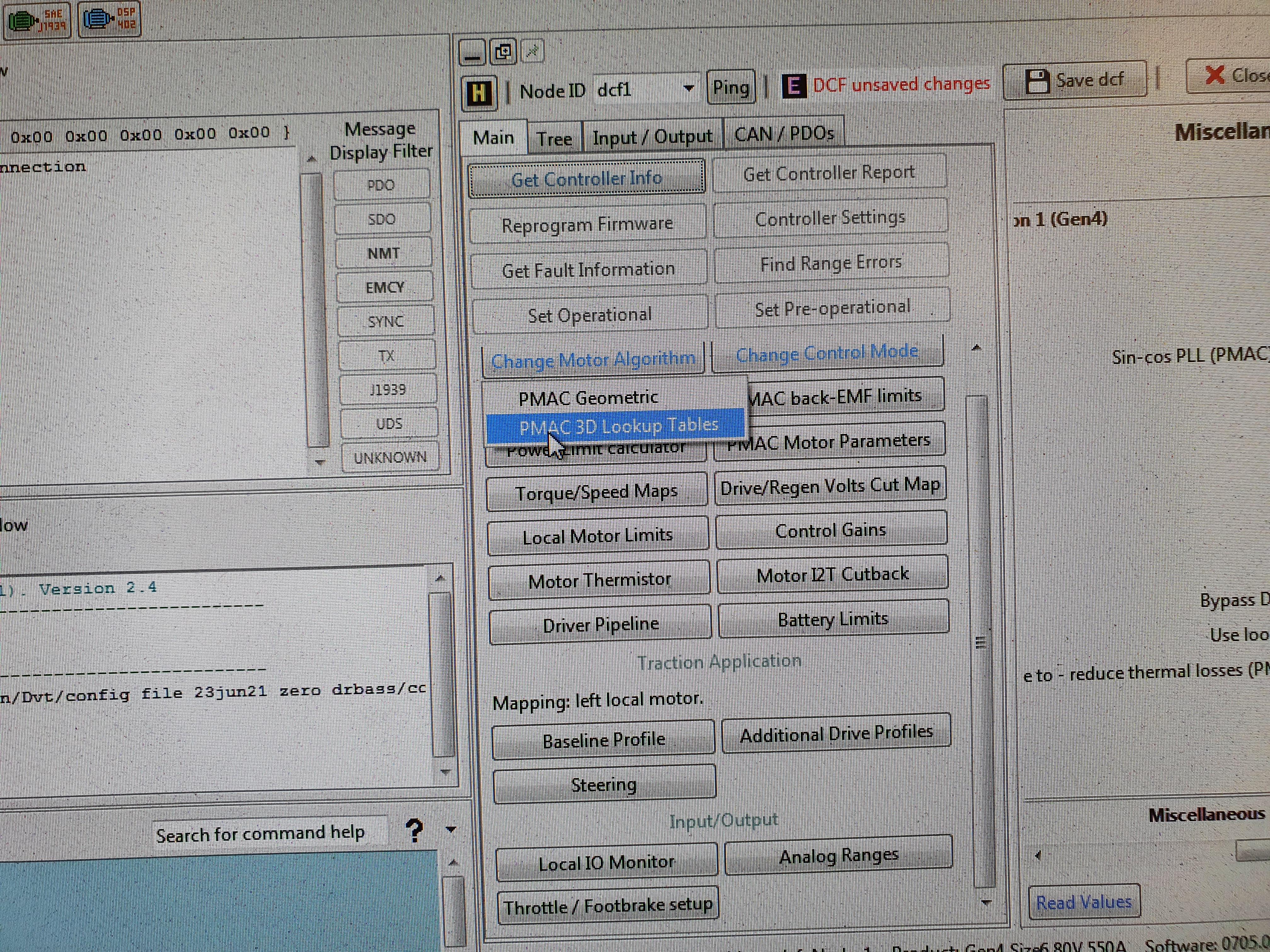
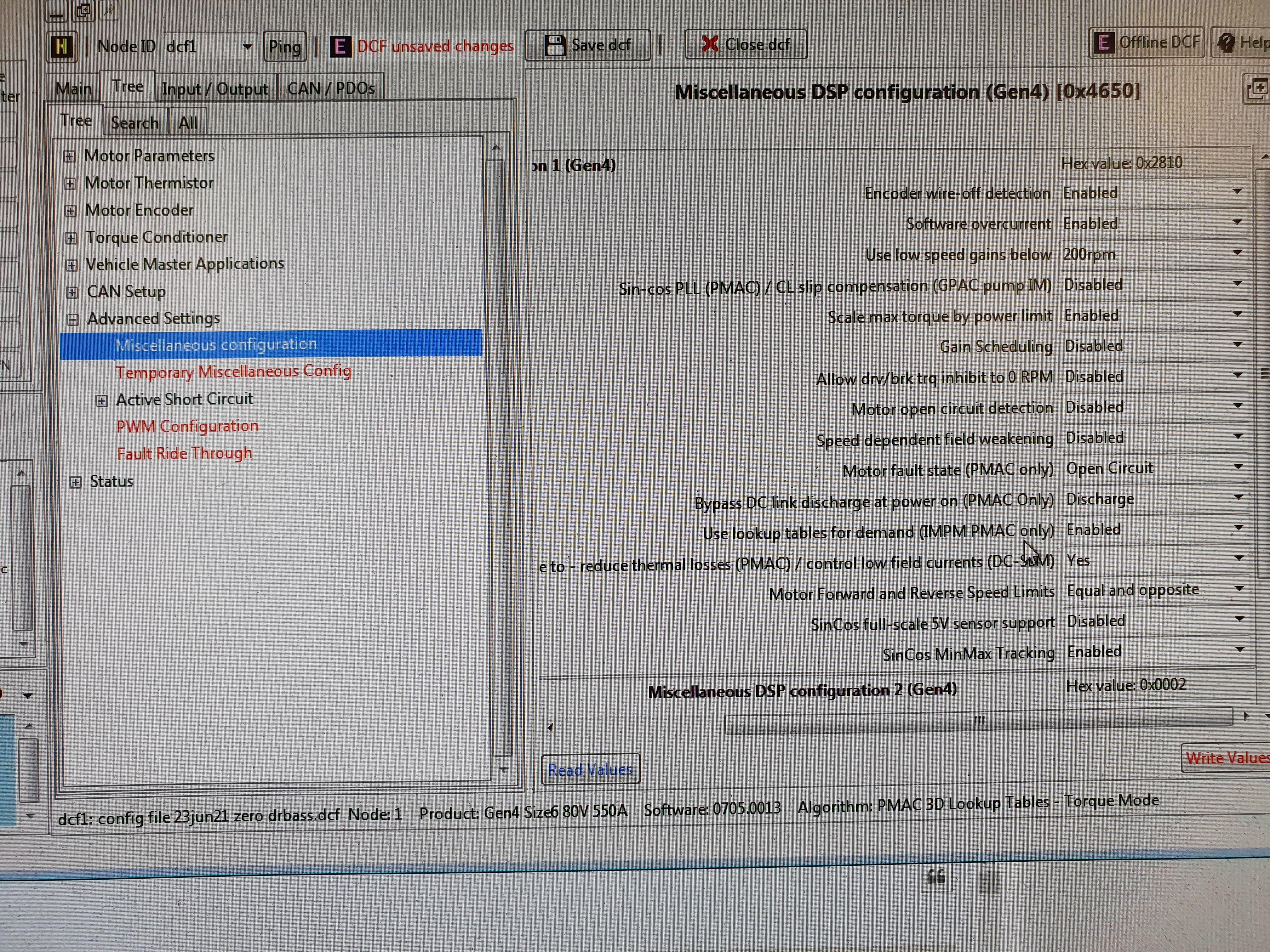
From a high level, You would use the Sevcon DVT software with an IXXAT usb-serial converter that was used to program the controller in the first place, and add your exported variables to the TPDO channels in the TPDO tab. The controller needs to be in pre-op to save changes.

Finally, verify the variables are now shown in the "vehicle monitor" window. This will also help you determine the scaling needed in your receiving node.

These steps are explained better in a Sevcon app note about programming rpdo/tpdos, but I don't have a link available right now. It's Google searchable though. Good luck!

Sent from my SM-N770F using Tapatalk

 
https://drive.google.com/drive/folders/1nUUMtkdexN3KlQtFg4FSIh-sc6PuDAqG?usp=sharing

Here's a list of documents I've found online by directly googling and downloading. I also just re-read through Thierry Lequeu's incredible writeup and I think I just answered my previous question. It read to me like you need to use the DLD files to add new PDOs. There were a handful of additional document titles at the end, I believe it's worth directly reaching out to him to see if they can be bought/made available.
 
Trying to setup a UVW encoder, does anyone know what the object names for these are to setup in the PDO section so I can view them in the Vehicle Interface?
 
good afternoon everyone, help me fix the error connecting the analog input 0x5182 thank you for any help
 
sevcon fault.PNG
aleks68 said:
good afternoon everyone, help me fix the error connecting the analog input 0x5182 thank you for any help

You will need to check your analog input configuration from within DVT and check each pin with a multimeter to confirm they are within the allowable range.

Edit: And a footnote, if you don't have a listing of sevcon Gen4 error codes you can type into the CLI "fault_info 0x5182" and it will tell you the same thing.
 
hello, kiwi, thanks for the answer, I will tell you the background, this motorcycle zero 2014 is out of order bms because in our country it is impossible to find any components or a dealer, I assembled a new battery and put ant-bms, the throttle stick consists of 2 electronic potentiometers, I removed the mbb from the motorcycle and connected all the wires to the controller but got stuck with the analog input settings, so I ask for help from people with experience in the settings with sevkon, I think this information is useful to many site users, In the photo, my configuration settings, thank you all.PS at the outlet of the throttle handle 4.3v.
 

Attachments

  • IMG_20210811_093730 (2).jpg
    IMG_20210811_093730 (2).jpg
    441.1 KB · Views: 2,373
  • IMG_20210811_093903.jpg
    IMG_20210811_093903.jpg
    497.9 KB · Views: 2,373
  • IMG_20210811_093929.jpg
    IMG_20210811_093929.jpg
    458 KB · Views: 2,373
66sametk@gmail.com said:
Good day everyone, I'm Samet. we are the university electric car team in turkey, we have difficulties in reading information from the motor driver while making an electric car. To give details, we are using sevcon gen 4 motor driver and we are trying to get information from sevcon gen 4 with canbus shield, but we can't get any information. Our aim is to reflect information such as motor speed, torque, battery status to the screen with canbus shield using arduino. Can you help us with this problem? How can we extract information from Sevcon gen 4 for arduino?

Probably a little late, but I use a script based off https://github.com/dexterbg/Twizy-Cfg for programming my Gen4 (DCF files). Sou you can definitely read (and write) what you want. No need for an expensive IXXAT adapter.
 
Needing some contactor wiring help. I have a Gigavac GX11HB, it has leads for the coil marked X1 and X2, from my understanding these will go to pins 3 & 4 on the controller, but I'm not sure which go to which, X1 to 3 and X2 to 4, or opposite? Not sure which is the low side of the contactor, X1 or X2?

s-l1600.jpg
 
So the Sevcon has coil suppression built into it for the contactor correct? I think this is part of my problem as my contactor also has a suppression diode built in. Is there a way to make these two work together or do I need a contactor without a suppression diode?
 
Sorry to hear, but yea I believe your only course of action is to either remove the contactor's diode if possible or get a different contactor altogether.
 
darseygodwin said:
Sorry to hear, but yea I believe your only course of action is to either remove the contactor's diode if possible or get a different contactor altogether.
Thanks for the response, any suggestions? I have a Size2 and am wanting to pick up a Size4 or Dragon 8 after I get this one up and running. I have been looking at the TE LEV100 for the Size2.
 
Doctorbass said:
tomaj said:
I still have not manage to set sevcon to operate with ME1302 motor. Motor spins up to 1000RPM and starts to oscillate. I have uploaded dcf file for this motor. Settings are for 80V nominal voltage but I run it on 105,6V.

Firstly I have to set encoder offset in DVT. I have no idea how to do that. There is nothing about this in the manual. Heeeelp! :mrgreen:


Thomas, PM me your email I will send you the document for that :wink:

Doc
I have the same problem with my ME1302... low speed is OK, but over around 1000 or 2000 U/min the motor start to oscillate. I changed many parameters, but no sucess..
 
rider119 said:
__

Thanks for the response, any suggestions? I have a Size2 and am wanting to pick up a Size4 or Dragon 8 after I get this one up and running. I have been looking at the TE LEV100 for the Size2.

I use the LEV200. The contactor welds quite often if it trips under load while I'm pushing the tuning profile, but that's to be expected when it arcs with that much load, especially over 96v operating voltage, so I can't really complain about it.

the LEV100 is only rated for 100A continuous, so even with a Size2, that's not enough. The LEV200 is a better choice for you. The coil voltage is important to consider, and is highly customizable within the controller settings. Keep in mind that that coil voltage is chopped from B+ down, and switches at a high frequency, inducing some noise in the system that can affect a sin/cos encoder if not properly shielded. Just make sure to shield the lines and it'll be fine, otherwise use a full line voltage coil. Be mindful when setting contactor parameters in DVT, line coil voltages will cook a low voltage coil very quickly. (speaking from accidental experience)
 
I'm having trouble finding the hall encoder and phase wire combo that gives me positive values in the Vehicle Interface. I have tried all 36 possible combos 3 times now with no luck. I'm not 100% sure which of the values I should be looking for on the phase/motor side of things. Is it the Iq Target (TPDO address 0x4600,6 , Iq_ref is how it is labeled on my version of DVT it seems) or Iq (TPDO address 0x4600,8) what I need to be looking at?

Iq Target gives me clear values if I rotate the rotor by hand slowly but Iq is just constantly jumping all over the place. If I try to spin the rotor with a drill to get the rpms up it just stops giving me any values until I pull the drill off and it slows down near 0 rpm then it gives some readings for a split second and makes the "white noise" sound. Also makes the "white noise" sound when I rotate it by hand.
 
@rider119, the best strategy is to use an oscilloscope between the motor's phase leads, disconnected from the controller. There is an app note for doing this from Sevcon, I posted a link a page back in this thread, I know things get buried quick here. I also think it's easier to use an external 5v supply on the encoder itself (or whatever your encoder is supplied with) an older usb phone charger is 5v.

So, if you had a multi channel scope, you could do it all at once, but even with a single channel you'd just have to mark the physical shaft angle. So with at least 2 channels, you measure say, positive lead on phase 1, and neg on phase 2, and the next channel on the encoder sin or cos wire. (Pos on signal, neg on encoder ground) As you manually turn the motor, you'll watch the sin waves and that will show you the relative phase offset between them. Switch motor phases (pos ph2 and neg phase 3, etc) and that will be another 120 degrees out, in one direction or the other, giving you the knowledge of which direction the motor is supposed to be strung up.

Iq target is the goal, but if the offset is all wrong, then the controller will be all fd up trying to figure out what to send to the motor because it wont react the way it expects. I think that's what you're seeing. The method to use the scope to measure and record all those things is available in the Sevcon app note I mentioned before.

Cheers
Darsey
 
darseygodwin said:
@rider119, the best strategy is to use an oscilloscope between the motor's phase leads, disconnected from the controller. There is an app note for doing this from Sevcon, I posted a link a page back in this thread, I know things get buried quick here. I also think it's easier to use an external 5v supply on the encoder itself (or whatever your encoder is supplied with) an older usb phone charger is 5v.

So, if you had a multi channel scope, you could do it all at once, but even with a single channel you'd just have to mark the physical shaft angle. So with at least 2 channels, you measure say, positive lead on phase 1, and neg on phase 2, and the next channel on the encoder sin or cos wire. (Pos on signal, neg on encoder ground) As you manually turn the motor, you'll watch the sin waves and that will show you the relative phase offset between them. Switch motor phases (pos ph2 and neg phase 3, etc) and that will be another 120 degrees out, in one direction or the other, giving you the knowledge of which direction the motor is supposed to be strung up.

Iq target is the goal, but if the offset is all wrong, then the controller will be all fd up trying to figure out what to send to the motor because it wont react the way it expects. I think that's what you're seeing. The method to use the scope to measure and record all those things is available in the Sevcon app note I mentioned before.

Cheers
Darsey

Darsey,

Thanks for the response. Yes, I really should pick up an o-scope and they're not all that expensive for a good used one, but ~$500 for something I will not use much is still a bit difficult to justify. Anyway, with the help of some other knowledgeable people I finally got it going. I misunderstood how the I/O setup works, I had 5 pins mapped but only had 3 in the # of inputs field, I thought it would only read the first 3. Anyway, I unmapped everything but the forward switch and set the # of inputs to 1 and it works! Now to spend lots of time fine tuning.

Another question, I also have a Dragon 8 controller that is password locked. Anyway to get around that? Could I pull the .dld file from my size 2 and upload it to the D8 along with the .dcf file? I don't know how cross compatible the files are between different models, I'm afraid they are not.
 
Hi guys!
I want to find dld firmwares for my SEVCON GEN 4 controller which has not sin/cos driver.
My small controller nameplate.jpg
It has abbility to work with induction motor or with pmac motor with Halls.
I want to try to tune both types of motors.
I have some firmwares and a lot of DCF files. But more of it for PMAC motors with sin/cos encoders.
DLD.jpg
May be anybody has dld and dcf pare from working motor with UWV encoder or for induction motor?
Somethig like below.
Difefent types dld.jpg
I have a lot of tech tips for sevcon controllers and ready to exchange.
 
Is there a way to get the .dld file off the controller? I do have a Gen4 Size2 running a QS120 motor running off of halls (UVW). I can send you the .dcf file, just don't know how to get the software (.dld) file off of the controller.
 
rider119 said:
Is there a way to get the .dld file off the controller? I do have a Gen4 Size2 running a QS120 motor running off of halls (UVW). I can send you the .dcf file, just don't know how to get the software (.dld) file off of the controller.
DVT help says:

Comands to load:

load -- Load a binary file into any of the memory spaces - assumes bootloader is running
load_dld -- Load a dld file into memory spaces specifed - assumes bootloader is running

Comands to save:

save -- Reads data from a memory space and stores it in a file - assumes controller is in bootloader

Comment from DVT command window: command format "save node_id section binfilename"

My mind says that Using of command "save" in bootloader mode must save dld code to file.
I don't know what to tipe in part of command "section" ???
 
Salient PMAC injection/characterisation

Im trying to find where to setup an IPM motor.
I find the "3D lookup table" under "change motor algorithm" here:

MI7BMu4.jpg


And I also find this:

JYCPjMI.jpg


(Where the arrow points) When I activate the change algorithm this goes from disabled to enabled. I can also enable it myself without changing algorithm, either way the motor dosent run afterwords.

Anyway, I dont find any 3D tables to be able to adjust.
The only thing I find is this:

l5b5lPc.jpg


I dont find any information in the manual, and I dont know the password.
Anyone here with experience of this?
 
Hello Everyone,
I am a motor designer working on IPM motor project for EVs. I am trying to integrate an Interior Magnet - PMSM motor with Sevcon Gen 4 Controller. I have done all the initial characterisation and have done some runs on Dyno using PMAC Geometric algorithm. With Geometric algorithm, the controller was able to calculate the Id limit which is matching with the design parameters. But it is not able to predict the value of Id correctly at multiple operational region of the motor. Its shooting up to peak Id limit rather than the required Id current for that torque input command because of which motor loops are unstable and efficiency is low.

One way to solve this problem is to use the Interior PMAC 3D lookup table algorithm instead PMAC geometric algorithm. I have all the necessary data for the 3D lookup table but I am not able to input it in the controller and I don't see any other way to edit the look up table. The following error (Image attached) is popping up on trying multiple file formats. Does anyone has any experience on how to solve this or work around it in some way.
Thank you very much.
 

Attachments

  • Sevcon 2.png
    Sevcon 2.png
    200.1 KB · Views: 839
Brilliant members here have given up on Sevcon, they are hostile to DIYers.

If your company plans on buying them by the container, may be different.

Personally I would think that expertise should be available at say $600 per hour from a certified distributor but apparently not.
 
Maybe Flight Systems can answer your question.
They were helpful with Curtis controller products and repairs I've purchase from them in the past.

https://shop.fsip.biz/en/catalog/node/controllers-sevcon


ShivamBhatia said:
Hello Everyone,
I am a motor designer working on IPM motor project for EVs. I am trying to integrate an Interior Magnet - PMSM motor with Sevcon Gen 4 Controller. I have done all the initial characterisation and have done some runs on Dyno using PMAC Geometric algorithm. With Geometric algorithm, the controller was able to calculate the Id limit which is matching with the design parameters. But it is not able to predict the value of Id correctly at multiple operational region of the motor. Its shooting up to peak Id limit rather than the required Id current for that torque input command because of which motor loops are unstable and efficiency is low.

One way to solve this problem is to use the Interior PMAC 3D lookup table algorithm instead PMAC geometric algorithm. I have all the necessary data for the 3D lookup table but I am not able to input it in the controller and I don't see any other way to edit the look up table. The following error (Image attached) is popping up on trying multiple file formats. Does anyone has any experience on how to solve this or work around it in some way.
Thank you very much.
 
Back
Top