Eastwood said:
Jrbe said:
For #2, as long as there's consistently enough airspace up top, you could do like they do with headlights, differentials, etc. Add a tube that goes up, 180° down, then cut at least 1" below the height of the opening. That should prevent siphoning when it goes upside down but will leak some. The more burps of oil the higher you'll have to go with the top of the loop.
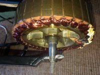
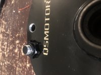
Do you have an image of what you’re explaining? I’m trying to picture a visual of how that would work with a hub motor. I know with Diff Breathers they are normally ran up to the engine bay. Maybe with a hub motor you could have an air hose vent out the same side of the axle where the wires come out.
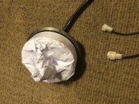
A simple version will probably be enough. But if it tips the wrong way the fluid will all drain out. It would be pretty easy to make a longer one (goes up more) if needed.

For a fuel cell something like this antisiphon loop allows liquid that splashes up to drain back into the reservoir. It might leak a little bit but won't leave a huge puddle from siphoning (if the hose goes below the normal bottom of the liquid level) if you flip. I have no idea how environmentally friendly statorade / ferrofluid is. The fuel filter they mention is used as an overflow catch can to trap any "burps." You can do anywhere from a simple / short version shown above to the all out antisiphon loop pictured here,
From https://www.pirate4x4.com/threads/racing-fuel-cell-tech-article-by-billavista-pirate4x4x-com.2702746/

You can print the picture and rotate it to see how it would always break the siphon.
There are tipover valves that could be ideal for a bike if they weren't so big. Idea is when upright the ball sits in a place where it can vent. When upside down the ball blocks the vent. Normally these would be installed vertically.
You might find something like these to put in a hose horizontally that would block the line if it's on its side. I'd guess you would need 2 in opposite directions. But they would need to be able to vent while sitting horizontal. They might rattle..

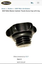
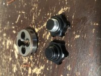
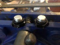
Most drain plugs are zinc plated. The zinc will oxidize when you weld it and can make you feel really sick. It also would likely make the o-ring seal surface less than ideal. Do you have a tool kit with a wrench or Allen key that could fit?
Might be able to grind the hex into a thumbscrew but you could still burn the zinc.
"Thumbscrew o-ring" as a search term found these, http://www.tsracing.com/Bead-Lock-Screw-Knurled-Black-Aluminum-5mm-x-8mm-P8053.aspx

You could probably find some good options.
Might be worth picking a thread size first that works for all options in case some don't work out.
..edit..
And this is probably the simplest solution. Short loop with a rollover (free floating ball) valve in it,

Most pcv valves are junk but you might find one that works out as your threaded rollover valve. Then you just need the hose loop.