I'm kinda stuck

Hi syukanzaki,

Having read in this thread about a display and power switch. Is your second controller being "energized" thru an ignition circuit properly? This is needed to power up its own internal 5vdc regulated power source, required for operation.
Just battery power connection to it may not be enough?

Checking for any 5vdc voltage out of the second controller would verify this. Like at the motor's hall sensors power input connector, or it's throttle supply power that you won't be using with the dual set-up.


Regards,
T.C.
 
Thank you TommyCat.
you're right maybe key switch.
that's why I don't hear tick sound from 2nd controller when key is on.
PXL_20220609_085617906.jpg
hardest part is finding wires from them again.
problem is main cable, controller and others are all moduled but use different colors.
I will never use moduled cable again...

positive, negative and white is throttle signal.
so positive and x(correct wire) reading should be 0-54v when key is on/off?
 
3 wires (2 from key switch, positive and switch and throttle signal) should be shared both 1st and 2nd controllers, am I right?
 
I start feeling like dual throttle setup is nice too.
If I can find 1T4D cable, dual throttle setup is probably the easiest way
but I've never seen on the market.

I'm not familiar w/1T5 cable but it has 9pin male connector as same as 1T4D.
Is it possible to use 1T5 cable instead of 1T4D cable?

1T4D has:
1x 2pin brake
1x 6pin display + brake
1x 3pin throttle
1x 2pin key switch

If I can just use 1T5 cable only ignition and throttle for 2nd controller, I'd rather go for dual throttle.
Display 5pin for on/off can be used for key switch too? and which wire? (I guess normally red, black, blue, green and yellow.)
 
syukanzaki said:
Display 5pin for on/off can be used for key switch too? and which wire? (I guess normally red, black, blue, green and yellow.)

What display do you have?

In order to get the one controller to work. Do you have to first turn the switch "on", then power up the display?
 
display.PNG
This display.

>Do you have to first turn the switch "on", then power up the display?
Yes, display doesn't have on/off. Key is on, display is on. (key switch is 2 wires.)

So my plan if possible is using 1T5 cable for 2nd controller line separately,
only for throttle, and key switch (this is I'm not sure I can use 2 out of 5 wires of 1T5 display line for ignition.)
or my display (this is also I'm not sure I should use only 2 lines for power up, or I can simply connect all 5 lines but this probably makes display confused.)

Biggest problem is all parts and cable have waterproof moduler connector, and controller is fully silicone molded. +all parts wires use all different color.
Once I cut off connector, it's super hard to find out which wire is what. (besides opening splitter part is almost impossible.)
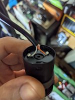
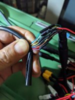
So I keep a connector to controller and open in the middle.
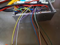
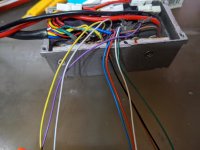
PXL_20220609_085617906.jpg
I cut off connector only this controller. (I have 2 more.)
these 9 wires going to key switch, display, brakes and throttle.
what I'm worried about is even I use multimeter finding 2 key switch wires, 0/54v read on multimeter could possibly be some other wires?
I guess brakes and throttle use 5v line, and key switch and display probably share same power line, so I don't need to worry?
If only key switch is 0/54v read in these 9 wires, I don't need 1T5 cable.
 
Your concern for not wanting to mix up the battery voltage (54vdc) and the 5vdc regulated controller power and it's electronics is warranted. These wires must not be crossed :warn:

By switch, do you mean the one on the front of your display assembly? Where you press the power button to turn everything on?
Note: I see that the switch symbols are different from the reference below... Do you have a separate power on switch?

At this time, using the display reference below, this is how I see parts of your system.

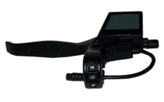
Your display/brake lever assembly has a 7-pin connector. Which would likely include these wires.

1) Batt+..... Full battery voltage input, that when switched by turning on the display, goes to "key" wire.
2) Key (AKA Ignition or control) Gets full battery voltage when display is powered up.
3) Ground... may be tied in with other components for their operation. Battery negative.
4) TX... Data transmit line. (low voltage electronic communication) intermittent voltage less than 5vdc when controller on.
5) RX... Data receive line. (low voltage electronic communication) intermittent voltage less than 5vdc when controller on.
6) Light positive power. Energized by light on sequence by display switches. Controller on.Typically, 5vdc or less.
7) Brake signal. Low electronic voltage signal, that when shorted to ground, stops motor output. 3.3vdc or so when controller on.

As you can see, a miss directed high battery voltage input to the wrong place would likely be very harmful. :(

Your throttle is also low voltage.
1) 5vdc controller input with controller on.
2) Ground (may be shared with ground above as mentioned.)
3) throttle signal (.8 to 3.6vdc typ.) with controller on.

Since you have a working controller with all exposed wires. You should be able to tell which is which by testing voltages.

Starting with the ignition "on" circuit. Then work thru and label off, light power, throttle power, ECT.

Then transpose those findings, to the original pinouts of the connectors if desired. Being very careful to transpose one side of a connector (male) to the opposite side (female) because the pinouts will be mirrored!


For the minimal wires to #2 controller using one throttle and one brake input...
Power to "Key" wire. (Tied in with display "key" wire.)
Throttle signal. (Tied in with #1 throttle signal out wire.)
Brake signal. (Tied in with #1 brake signal)
Battery +
Battery -

Note: With controller #2's display missing and bypassed. Some switch functions will not be available. Obviously, PAS power setting for one.

Recommended precautions...

Keep all wires and test probes from touching.
Double check readings before connecting.
Perhaps put a 100mA fuse in line with the battery power control wire. May help if a mistake is made.

Any questions, or if I'm not clear on or wrong on a point, please let me know BEFORE wiring/trying!

Display reference used...
https://www.sharpbike.com/product/electric-bike-brake-lever-with-lcd-display-160pdd/
 
Thank you TommyCat.

First of all, display looks like exactly same model but mine doesn't have power button.
So display is not 7pin, but 6pin. (I guess it's just bypassing key to power.)

cable.PNG
and this probably makes lots of ppl misunderstand.
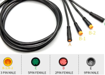
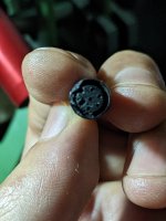
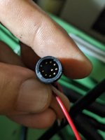
All connectors are like this (this is 1T5 cable) and tips are kind of solid plastic piece, so it's very hard to check wire positions.
(+ even if I can open it, I only have 9pin motor connector diagram but I've never seen 9pin 1T4D connector diagram.)
So I opened cable line side to check voltage. (this is like blind test or russian roulette but of course only for test.)
This is why it's always very hard to figure out how wires are connected. (ex. throttle, cable and controller use all different color of wires, so I tested with throttle negative and all controller's 9 wires to find throttle signal wire but this was kind of easy because 0.8-5v is only one possibility.)

Also the picture of controller is just to show how wires are.
This controller was for 2nd controller when I connected only throttle wire, connector is already cut off.
I can not use this controller for test.

What I was trying to do and I was anxious about was, if I check voltage to find key switch wires from those 9 wires (throttle signal wire is already confirmed so 8 wires, and positive wire should be red so positive and 7 wires?), is there any possibly 0/54v (key off/on) wires other than correct key switch wires? (Display, brakes, throttle and key switch.)
My guess was key switch is only 0/54v possibility because brakes and throttle use 5v line, light on/off also use 54v but this doesn't matter when it's off, and display doesn't have power on/off should be through key switch.

Key switch side only has 2 wires, so this is very easy to bypass from there when I connect to 2nd controller. (my previous question about bypassing from display was wrong. Please forget it.)

My unclear explain probably made ppl confused.
I'm very sorry.
 
I agree that at least two wires would carry the full battery voltage or high voltage would be the Batt+ supply wire to the key switch, and with the switch on, the Key wire returning high voltage back to the controller. It also must get sent to the display. So, 3 wires of the 9 main control harness with High voltage with switch on?? Or it could just be kept in the harness.
Checking the harness by resistance testing (no voltage) will show you what is connected to what...

Only others I can think of...

5vdc throttle voltage
Throttle signal
Brake signal voltage
Batt negative or ground
RX data line
TX data line

I'm missing explanation for one wire...?

I highly recommend you making up a diagram to work off of. Doesn't have to be as detailed but something like this...

fetch


Would help you, as well as other trying to follow along. And then you would have a good diagram of your system.

Sure would like to see the 1T4 harness you are using now, and it's connector pinouts, and its peripherals.

What do your display buttons do? Do you have a link to your manual? You have cruise or PAS functions?
 
Thank you TommyCat always.

I have same picture and tried to make diagram myself.
But the problem is Bafang uses different diagram and different wire color combination, this always makes me confused.
1T4D cable manufacture is "JUNYU" and most other parts manufacture is WuXing (Star Union).
I've contacted WuXing directly couple times but they don't show any diagram or detail.

This is just one example.
PXL_20220628_002338986.jpg
PXL_20220628_002300171.jpg
Key switch has white and orange wires but there's no orange wire in either cable or controller, and white wire in cable and controller is throttle signal wire.

I understand I have to test all wires.
I just didn't want to open wires again (as much as possible), so that I was trying to figure out the easiest way.
If I can buy another 1T4D cable, 2 throttle setup will be the best way for sure.

This is display + left brake connector (sorry for mess I tried to open).
PXL_20220628_004653688.MP.jpg
and this is 9pin cable-controller.
PXL_20220628_004737085.jpg
This looks exactly same as 1T5 (so I was trying to use this instead) but diagram should be different.

And this is LDC manual. (middle button is light instead of power.)
View attachment free ride lcd manual.docx
 
I start checking all wires now.

I'm just wondering one thing.
Reading from key switch:
When key is off > 53.2v
Turn on the key > 0v (display on, motor on.)
This is opposite from my expectation.
Is this normal?

This means key switch doesn't "connect" power through, but it shuts out and relay?
 
Are you reading one side of the key switch to the other? = 54vdc off,0vdc on…?


Or have meter black lead on battery negative, and probing both sides of the switch with the red probe? = One side of switch 54vdc with battery connected. Other side of switch 54vdc with switch turned on…?
 
>Are you reading one side of the key switch to the other? = 54vdc off,0vdc on…?
yes, orange and white wires on the key switch picture I posted.
54v when it's off, 0v when it's on but everything works ok.
 
A meter reads the voltage potential between two points.
With the switch open you have a potential of 54vdc between the two points. (Power on one side, 0vdc on the other side.)
With the switch closed, or making a direct connection between the two sides of the switch, you have 0vdc potential.

I recommend you test for voltage in your harness (and else where) with the meter’s black lead on the batteries negative terminal. (Or similar easily accessible negative battery or ground spot)
Probing with the red one.
 
WXtrtl.PNG
WXctrl.PNG
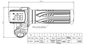
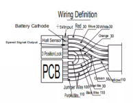
I found this WuXing display diagram.
This probably shows the same diagram except orange. (There's no orange but gray.)
Yellow might be brake signal?

Brown and Gray are switch lines which is 54/0v : off/on.
Now I connect Brown, Gray and White (signal) but still only 2nd motor doesn't work.

Is there any wire I must not or no need to connect 100% to 2nd controller?
If not, I just wanna connect all 9 wires and test.
 
>A meter reads the voltage potential between two points.
With the switch open you have a potential of 54vdc between the two points. (Power on one side, 0vdc on the other side.)
With the switch closed, or making a direct connection between the two sides of the switch, you have 0vdc potential.

oh...yeah...why I was doing so stupid, such a elementary school level mistake...
I'm very sorry TommyCat.
I should be going crazy working on this too long.
 
Ok, one throttle is blown by mistake but finally 2WD works perfectly!

I still have lots of exterior work but hardest part is done.
Thank you all, especially TommyCat.

I use base model and customize, not full scratch.
I shouldn't post pics here when all done?
 
Hallo
Have any ideea of manual for this display, or to help me with some information :
This is a new version for e-bikes with 5 gears. It’s not only the label difference “+/-/ON-OFF“ from the 3 buttons, but also different sections & display range for some of the P codes.
Thanks
 
Back
Top