Improving original firmware - TongSheng TSDZ2 mid drive motor

hurzhurz said:
Sure, no need to risk it beforehand ;)

If you want to try $5b / $0c (or anything else) before it is fixed included, just write this to the eeprom:
0x4010: "00 5b 00 0c"
Do you mean anything additional with PAS cadence then cadence candidates $04/$18?
By the way, I think they just shows something when rotated forward.


Oh, and I have opened my motor now.
I can say, the humming comes from the torque sensor or the coil.
When I unplug it and I measure constant 12.5V at the plug... I think that is not ideal?
You say something about 5V/20us pulses on your website...
Well, and there is an inductor that looks a little bit toasted as far as I can see through the "epoxy".
I mean having direction rotation of pedals can be nice to debug if there are issues.

5V/20us on the microcontroller pin but on coil it has a very different shape wave. Only good to see with oscilloscope, I don't know what a multimeter can measure.

If torque sensor is not working, maybe you can use the throttle for now. A simple variable resistor can work as a thottle.
 
Yeah, I will check what flags/bits are probably useful about PAS. While watching the memory dump, I had seen 3 bytes that probably contain something.

Ah ok. I will also check the output pin when I have scraped away the epoxy.
I don't need the bike soon... in fact, I haven't used it lately... so I can try fixing it without any hurry.
And by the way, I don't know how the legal situation is for you, but I think a throttle is illegal here (at least above 6 kph).
 
hurzhurz said:
And by the way, I don't know how the legal situation is for you, but I think a throttle is illegal here (at least above 6 kph).
Here in Portugal, very unfortunately, car drivers always drive over legal speed and often drive while talking to mobile phone :-( -- so cops have much more to do than enforce bicycles law.
 
hurzhurz said:
For the cadence, I have maybe identified registers $04 and/or $18 (maybe identical).

And battery voltage could probably be read from $1f.
Though, I'm not yet sure about the conversion factor... not enough datapoints as my lab bench power supply is capable of just 30V.
So, both $04 and $18 seem to have the same value: cadence / 2.
I didn't tested $1f for now.

casainho said:
Good news!! Finally we got pedal cadence :)

The first part of the video shows torque value and on second part (after I click on LCD power button with the hand that is holding the camera) shows cadence (but the value seems to be half of the cadence).

Next step is to calc the human power and also the Watts Hour of human power. I wish we could implement the disable of some information, so user can decide which information prefer - like cycling only over battery voltage, trip battery discharged total Watts/hour, trip human Watts Hour. I think we need to think on a "design" for all this information.

KT LCD3 showing the following data from TSDZ2 motor:
- battery voltage
- motor power in watts
- motor current
- trip total Watts/hour
- pedal torque value
- pedal cadence
- bicycle wheel speed
- motor assist level
- brakes state
- battery state of charge

[youtube]KsarWeFCn5A[/youtube]
 
Cool that you have already tested it!

And for $1f/battery voltage:
After I connected a LiPo battery in series with my lab bench power supply, I was able to take some measurements:
$1f / 2.9 = voltage
And some new findings:
$a2 contains the minimum voltage. It is the second byte from the eeprom (5A in my case, so 31V).
$a3 is the offset voltage for the battery status in the LCD, defined by $a2+9 (60 in my case, so 33,1V).
$6d looks to be the upper voltage limit, defined by ($a2/2)*3 (87 in my case, so 46,55V).
 
racingame said:
Great work, following with interest and waiting for a guide. :D
Thanks for the feedback. I hope to start writing the guide this weekend and put online on Sunday night.
 
This is the graph for the values on the big array, inside the original firmware. I can't understand well... but yes, SVM waveform is there:

 
You are rocking bro! It sucks that I am pretty much illiterate when it comes to this stuff but it is interesting and I am learning a little. Thank you!
 
great great job !!! will it be possible to use the 48v version even with 36v batteries? sorry my bad english !!!
 
alva78 said:
great great job !!! will it be possible to use the 48v version even with 36v batteries? sorry my bad english !!!
I think so but will need testers!!
 
If I can eventually figure out how to update the firmware I will try to test with a 52v battery (14s) and a 44v battery (12s).
 
hurzhurz, people are asking for changing parameters on firmware, that I think will be hard to do or we will always be limited...

So, I think we should invest to make our own firmware and I want to ask your help in understanding just a specific part of the original firmware that is the only puzzle piece missing for me to finish our own firmware.

See this video from my last state:

1st time running the motor with square wave - block commutation:
[youtube]O9shbfQ9hHk[/youtube]

After I went to use SVM (see the difference in noise!!), just like using the table values they use on original firmware (the 3rd last part of that graph):
casainho said:
This is the graph for the values on the big array, inside the original firmware. I can't understand well... but yes, SVM waveform is there:

[youtube]EonFwTk2cs8[/youtube]

So, as I expect they are using a kind of FOC, I mean, they are for sure writing 3rd last part of that graph to the PWM and adjust with the increase of motor current and speed. That values in amplitude are multiplied by the throttle value, possible by a current controller. Anyway, should be easy to see that table values to be multiplied before go to the PWM.

The big puzzle missing part is the phase: they are for sure increasing / decreasing for some rate the index when reading from that table and that way adjusting the phase voltage. Also, they should put at TIM1 PWM channel 1, 2 and 3 the same value in amplitude but 120 degrees phased out... like if the array has 360 values in total, index for PWM 1 can be 0, index PWM 2 can be 120 and PWM 3 240.

We need to figure out the math they are doing to define that rate of increase/decrease of the index. Maybe it is even only some switch for increase or decrease the index. And I am pretty sure it will depend at least from the motor current...
I was expecting that they need to use sine/cosine and they would be using a look up table / array with that values but I didn't spotted that on the firmware....
Can you please help on this??

The firmware sources are here: https://github.com/OpenSource-EBike-firmware/TongSheng_TSDZ2_motor_controller_firmware

casainho said:
jur said:
casainho said:
Thanks for the info. For now, I think that even with float operations, for the measured times on my experiences, it should work. Optimizations can come later.
Could you please state exactly what you need for solving the math:

Inputs, equations to solve and required outputs. I am deep into generating the simplest possible math operations but it would be most efficient if you could please spec what you need.
Looking at the documentation from Shane Colton here:
- https://opensourceebikefirmware.bitbucket.io/development/Motor_control--FOC--Shane_Colton_documentation_and_firmware.html
- https://github.com/EGG-electric-unicycle/documentation/blob/master/Shane_Colton/3phduo.pdf

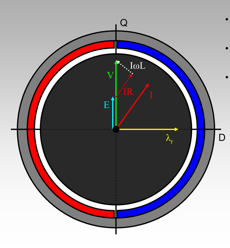
1. Without align current with BEMF (inefficient controlling of the motor)
image.png


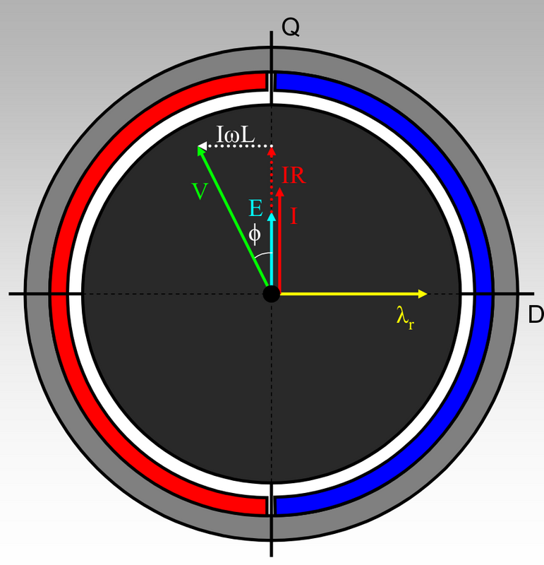
2. Aligning current with BEMF (efficient controlling of the motor)
image.png


I know that we want to be at 2.

I think as inputs we have:
- direction of Q axis, as we can measure BEMF by rotating the motor with our hands and BEMF direction is max value of the sinewave measured and then we can reference to hall sensors transition signals
- we don't know phi r (yellow vector) and I think we don't need it. It just represents north pole of one magnet of rotor
- I we can measure. I is the phase current however we just can measure battery current on the shunt and I phase current = I battery current * actual PWM duty_cycle.
- IR is I * motor coil resistance, that is why we need to measure the resistance
- E is the BEMF, which is motor constant of generated volts per RPM, and it can be measured but we know for our motors can be something near as 36V(48V) / 4000 RPM. Knowing the motor speed, that we can measure using hall sensors signals, we can calculate the E
-- phi r (yellow vector) is equal to BEMF
- IwL can be calculated knowing the I, motor speed and L motor inductance, that is why we need to measure the coils motor inductance
- V is the phase voltage we apply to the motor phases, and it is Vbattery that we can measure * currently PWM duty_cycle that we apply

As we can see angle teta increases with IwL and IR, so, depends from motor speed and current. We can measure both and we know that angle between IR and IwL are always 90 degrees. How can we calculate the angle on 1. so we can advance the phase voltage V by that angle value and I will be in aligned with E an so we will get the higher torque per amp??

On the second link for documentation of Shane Colton, he talks about some math to calculate the angle:
file.php

Please look at this message of Stancecoke: https://endless-sphere.com/forums/viewtopic.php?f=30&t=93818&start=50#p1375474

And please note that we don't need the angle value, we may just need to know if the angle is positive, negative or near zero. On Kunteng controller, in our firmware, we just do that and it works very well!! See here a resume: https://opensourceebikefirmware.bitbucket.io/development/Datasheets_and_application_notes--Endless-sphere.com_forum_messages--2017.10.23_-_FOC_and_no_FOC_comparison.html

This is all the I know for now. And the PWM signal on TSDZ2 motor controller is just the same as on Kunteng, that we already implemented and works very well. On TSDZ2, there is no phase current sensor and I think it is not needed because it just need to work with a specific motor with a know R and L values unlike on Kunteng that should work with most hub and even mid driver motors -- for instance, the PWM frequency on Kunteng is just the same 16kHz.
 
casainho said:
This is the graph for the values on the big array, inside the original firmware. I can't understand well... but yes, SVM waveform is there:

I wonder if they are precalculating some of the adjustments for load/speed/current that are done on the fly in the KT controller. It would be interesting if they did that to improve the performance or just because they are geared so much that the erpm was too high to run the calculation. Alternatively could the KT firmware be improved with a larger table?
 
-dg said:
casainho said:
This is the graph for the values on the big array, inside the original firmware. I can't understand well... but yes, SVM waveform is there:

I wonder if they are precalculating some of the adjustments for load/speed/current that are done on the fly in the KT controller. It would be interesting if they did that to improve the performance or just because they are geared so much that the erpm was too high to run the calculation. Alternatively could the KT firmware be improved with a larger table?
The motor runs at 4000RPM and that is near the 500/600 ERPM limit. They are using just the same 16KHz PWM frequency.

Maybe KT firmware can be improved with a large table... someone will need to test. That is not a priority for me.
 
Maybe a first hint to where interesting things could be:
There are functions to prepare the value that is written into the timer compare registers for the three channels: $8791/$87ef/$884d
These functions also lookup values stored in the flash starting at $8b32 and $949a.

And I think this happens at manly two occasions:
In the TIM1 capture/compare interrupt ($ad2f) with some checks/adjustments about current etc
In the Port C/D/E interrupt ($ac5c by calling $861f) a bit simpler when hall sensor, brake input or something changes?

Oh, and for me it looks like the PWM is just done on the positive side and the negative side is just switched in rough steps / just turned on for the whole negative part of the sine wave?
Updated in $a88b & $aa3c.
 
hurzhurz said:
Maybe a first hint to where interesting things could be:
There are functions to prepare the value that is written into the timer compare registers for the three channels: $8791/$87ef/$884d
These functions also lookup values stored in the flash starting at $8b32 and $949a.

And I think this happens at manly two occasions:
In the TIM1 capture/compare interrupt ($ad2f) with some checks/adjustments about current etc
In the Port C/D/E interrupt ($ac5c by calling $861f) a bit simpler when hall sensor, brake input or something changes?

Oh, and for me it looks like the PWM is just done on the positive side and the negative side is just switched in rough steps / just turned on for the whole negative part of the sine wave?
Updated in $a88b & $aa3c.
Thanks!! That piece of code seems a Déjà vu for me :)


And this what I implemented for KT motor controllers:
/****************************************************************************/
// calc final PWM duty_cycle values to be applied to TIMER1

// scale and apply PWM duty_cycle for the 3 phases
// phase A is advanced 240 degrees over phase B
ui8_temp = ui8_svm_table [(uint8_t) (ui8_sinewave_table_index + 171 /* 240º */)];
if (ui8_temp > MIDDLE_PWM_DUTY_CYCLE_MAX)
{
ui16_value = ((uint16_t) (ui8_temp - MIDDLE_PWM_DUTY_CYCLE_MAX)) * ui8_duty_cycle;
ui8_temp = (uint8_t) (ui16_value >> 8 );
ui8_phase_a_voltage = MIDDLE_PWM_DUTY_CYCLE_MAX + ui8_temp;
}
else
{
ui16_value = ((uint16_t) (MIDDLE_PWM_DUTY_CYCLE_MAX - ui8_temp)) * ui8_duty_cycle;
ui8_temp = (uint8_t) (ui16_value >> 8 );
ui8_phase_a_voltage = MIDDLE_PWM_DUTY_CYCLE_MAX - ui8_temp;
}

So $BC_$BF seems to be the table index (phase voltage angle) and $C0 seems to be the duty_cycle value.
And we can see that value is from 0 up to 250, so middle value is 125.

casainho said:

We can focus now on $BC_$BF, they should be calculated/adapted somewhere...

I also think that code should be called at each PWM interrupt/cycle. Or at other events, mainly after put duty_cycle = 0 or something like that.

About the negative PWM channels, I think they are configured to be just automatically the inverse as I do on KT controllers firmware as I recorded the PWM signals for TSDZ2:
- Example of PWM channel 1 and PWM inverted channel 1:
1-13.png

https://opensourceebikefirmware.bitbucket.io/development_tsdz2/About_Tongsheng_TSDZ2_mid_drive_motors--Motor_controller.html

I think they disable the N channels when they want to disable the power to the motor.
 
This piece of code is "dead", right? I don't see no one calling it....
As we see calls to empty functions, maybe that was a piece of code left from some testing/debug.

I wonder if the code were programmed in C or assembly...

 
casainho said:
This piece of code is "dead", right? I don't see no one calling it....
As we see calls to empty functions, maybe that was a piece of code left from some testing/debug.

I wonder if the code were programmed in C or assembly...
I saw this too... it's strange.
I can't imagine someone writes this all in assembler, but I also can't imagine a compiler leaves unused code.
Oh, and don't let you trick by a "ret" to think this is the last line of a routine. I have seen multiple with more then one "ret"...


By the way, looks like I was successful at fixing my controller. Had to replace this P-channel mosfet:
mosfet.jpg

Maybe I forgot to remove the battery one time while flashing and it was turned on for far longer then 20us.
The coil has a resistance of roughly 2 Ohm... at about 12V, this is a lot of current that must go through that tiny thing...
 
hurzhurz said:
By the way, looks like I was successful at fixing my controller. Had to replace this P-channel mosfet:
mosfet.jpg

Maybe I forgot to remove the battery one time while flashing and it was turned on for far longer then 20us.
The coil has a resistance of roughly 2 Ohm... at about 12V, this is a lot of current that must go through that tiny thing...
Good!!

casainho said:
This piece of code is "dead", right? I don't see no one calling it....
As we see calls to empty functions, maybe that was a piece of code left from some testing/debug.

So, now I think they were playing during development with using that 3 different waves but in the end they just use the last one, just like I do on KT firmware and TSDZ2 firmware. The array is really big and they didn't even care to remove it, so this firmware only in 16kbytes flash memory should be really minimalist.

I wish I could understand why TIM3 is used. I wounder if is something about a timer to "make" the SVM wave and if his frequency is adjusted depending on hall sensors frequency.
 
I have digged a little bit in the code again.

I think one main task of TIM3 is to check the hall sensor and to update the negative phase outputs according to the state.
This is done in $9a67: first $ab28 is called to read the state (and also stored in X), then $a99b is called to set the outputs according to X.

I also have the feeling that the counter of TIM3 could be used to measure the time between the hall sensor state changes, but I'm not sure about that.
Maybe $aedf calculates the relative position in the sine wave using TIM3 counter and stores it in $c1, $af29 uses $c1 to shift the sine-wave-lookup-indexes for TIM1 CH1-3, before $8791/$87ef/$884d do update the PWMs.


By the way, some other interesting things I came across:

$a7fd seems to check the assist level and probably sets limits according to them. Also according to the throttle.
It seems like there is actually an assist level below 1 that is selected by bit#7 in the flag-byte from the serial message. (Maybe you want to test it with you custom LCD3 firmware?)

$9f0f seems to to some error code stuff.
It checks some bits and sets the error code for the serial data message accordingly.
It also writes something like an internal error code to $34.
And as $34 is somewhere else ($a2cd) is written into the eeprom at 0x4006, I think my suspicion that this eeprom byte is used as an error code (for diagnostic or so) could be correct.
 
hurzhurz said:
I have digged a little bit in the code again.

I think one main task of TIM3 is to check the hall sensor and to update the negative phase outputs according to the state.
This is done in $9a67: first $ab28 is called to read the state (and also stored in X), then $a99b is called to set the outputs according to X.

I also have the feeling that the counter of TIM3 could be used to measure the time between the hall sensor state changes, but I'm not sure about that.
Maybe $aedf calculates the relative position in the sine wave using TIM3 counter and stores it in $c1, $af29 uses $c1 to shift the sine-wave-lookup-indexes for TIM1 CH1-3, before $8791/$87ef/$884d do update the PWMs.
Maybe TIM3 being used as a PLL Phased Locked Loop, where TIM3 is counting the time for implement the SVM. And has as inputs the hall sensors frequency and maybe filters a bit oscillations on hall sensors signal frequency. I do this in may code for KT firmware, but in a bit different way and without filtering the hall sensors frequency oscillations.

This is not yet "FOC".

hurzhurz said:
By the way, some other interesting things I came across:

$a7fd seems to check the assist level and probably sets limits according to them. Also according to the throttle.
It seems like there is actually an assist level below 1 that is selected by bit#7 in the flag-byte from the serial message. (Maybe you want to test it with you custom LCD3 firmware?)
Tested and it works -- please see my message on TSDZ2 main thread.

$a7fd, there is a comparison with $1c lower than 73? Why it would force assist level to be the max value of 4?? I just can think on throttle, that after a min value input, it would override the assist level and make it always at max value, as when using throttle we want max assist level.

I think assist level is used a multiplication factor of torque sensor value, that would be at begin of control loop (or at end of control loop, by being a factor to current level) --- each assist level seems to put a factor on $a6.

Code:
ld A, $1c
cp A, #$49
jrnc $a860  (offset=93)
that jrnc is testing if $1c is higher or lower than 0x49??

I thought that $1c could store the current value, as it is compared many times with values under 18. See the ADC value for current is amps * 5,

Code:
ld A, $1c
cp A, #$55
jrnc $b5ec  (offset=55)
0x55 = 17 dec

Also, $1c may be something like a target value of current, where throttle/torque sensor can be mapped target current value. Because seems $1c is increasing/decreasing, maybe at some rate...

In my code I have target_duty_cycle and duty_cycle. Duty_cycle is only increased or decreased, to get to target_duty_cycle but depends on factors like current controller and throttle/torque sensor inputs.

hurzhurz said:
$9f0f seems to to some error code stuff.
It checks some bits and sets the error code for the serial data message accordingly.
It also writes something like an internal error code to $34.
And as $34 is somewhere else ($a2cd) is written into the eeprom at 0x4006, I think my suspicion that this eeprom byte is used as an error code (for diagnostic or so) could be correct.
Good to know.
 
Back
Top