Invert ebrake signal

yopappamon

10 kW
Joined
Mar 31, 2010
Messages
825
Location
Most dangerous city in the USA, Flint, MI
I'm not sure how I missed this, but I made my own ebrake switches to go in Shimano V-Brake shifters. I used a reed switch and a magnet. JB Weld to mount everything. Works great, except it's a closed signal, open on braking. The controller expects open signal, close on braking.

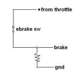
Will this pull down resistor arrangement work. Pull + voltage off the throttle connector. If so what value resistor? 1K?

Schematic
Brake.JPG
 
the e-brake line on most controllers has an internal pull up resistor. for this citcuit to work the resistor you add would have to be considerably smaller in resistance than the value of the internal pull up for it to work as a pull down. not knowing the value of the internal pull-up resistor it would be hard to give a value. but i would guess that something near 500R might work. if it does not there are other options

the easiest solution would be to use a Normally-Closed Reed switch. but if you are now stuck using the N-O switch a possible solution could be a 5V coil PC mount Telecom relay. most of these have a 10mA coil. surplus they are cheap. new they are pricey. they would not be my choice.

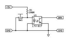
an opto isolator may be another option.
ExpressSCH.jpg

you can use almost any old Transistor Output Opto-Isolator. 4N25, LTV817, etc. the resistor is also not critical. values between 270R to 390R should work. but the lower values will draw more current. most of these opto's cost 25 cents each at electronic distributors.


rick
 
Hi Yopappamon,

All you have to do is to connect the ebrake yellow wire from the EBS- to the black ground wire to trigger the ebrake signal and stop the motor from spinning. :)

Rkosiorek, thanks for the drawing. I have learned something new from you today. :)

Regards,
Lyen
 
Lyen said:
Hi Yopappamon,

All you have to do is to connect the ebrake yellow wire from the EBS- to the black ground wire to trigger the ebrake signal and stop the motor from spinning. :)

Rkosiorek, thanks for the drawing. I have learned something new from you today. :)

Regards,
Lyen

Thanks for the answers.

Lyen, my problem is my ebrake is stopping the motor when I'm not touching the brake.

Thanks for the schematic, rkosiorek. That was going to be plan B, but I tried my circuit and it works. 10k resistor.
 
I think your ebrake lever(s) has an usual normal closed instead of a normal open switch. You may consider simply replace it with a normal open switch inside the ebrake lever. Anyway, whatever makes it easy and works for you is doable. :)

yopappamon said:
Thanks for the answers.

Lyen, my problem is my ebrake is stopping the motor when I'm not touching the brake.

Thanks for the schematic, rkosiorek. That was going to be plan B, but I tried my circuit and it works. 10k resistor.
 
A possible thought: Sometimes a second magnet permanently placed near the switch, with just the right polarity compared to the first magnet, may bias the switch to operate the opposite way (although ti may also require changing the orientation of the first magnet and/or the reed).

Alternately, you could change the arrangment of magnet and switch so they are on a part of the lever that moves in the opposite way from how it is now. Meaning, if it is setup to move the magnet away from the swithc now, use a part of the lever and body that would move it toward the switch instead.


Another way to do the second part if there is no place to do this on the lever is to do it on the brake line or brake arm itself, so that the magnet is moved relative to the switch in whatever way you need.

What do your brake arms look like?
 
good ideas, amberwolf

I just really didn't want to have to pry off any of the glue. It appears to be working fine with the resistor. The shifters are part of the brakes, so I can't use regular ebrakes.

file.php
 
yopappamon said:
I just really didn't want to have to pry off any of the glue.
Understandable. :) It's always so nice when you design and implement something, only to find out it's got to be done a different way to actually work. :roll: I kinda do that a lot more than I ought to. :(

Oh, if you ever need those optos mentioned above, you can find some in any PC power supply, sometimes three or four. Also in old UPSs.

It appears to be working fine with the resistor. The shifters are part of the brakes, so I can't use regular ebrakes.
I have a similar problem with DGA in that my front brake is a locking lever, so that I can keep the bike from rolling while I attach a trailer, or load the trailer, etc, or just to keep it from rolling around when parking it, etc. So I put a switch on the actual brake arms (or rather, on the cable).
http://www.endless-sphere.com/forums/viewtopic.php?p=277113#p277113
file.php

It ended up messier than that, with some extra zip ties on the brake arm to catch the switch when it slipped off the cable retainer during harder braking, :roll: but the basic idea was sound enough, and works. It drives a relay that switches both the brake line on the controller and the 12V motorcycle taillight's brake light.
file.php

I already had one that ran off the Fusin's hall ebrake, but the Lyen controller didn't have the 5V supply on the brake line, so I went with a second relay rather than modify the first, so I could swap controllers/motors at need for experiments or emergencies. :)

I will have the identical issue to yours once I get the cargo bike designed and built, as I want to use the combo levers that came with the Trek frame on it (once I do some major maintenance on them, as they're pretty grungy and missing covers, etc.)

THat switch is going to be changed to a microswitch with a wheel on it at some point, when I have time to make the bracket to hold the switch. It'll work a lot better than the existing one, as the wheel will be held in the pushed position by the brake arm itself until I squeeze the brakes, and then it will engage the NO part of the microswitch as it unpushes the wheel/lever on the switch.

I used reeds once on front and rear (for my brake lights, before I motorized it), but they cracked (I don't know why, since the speedo one on the front fork didn't). They were just bare reeds pulled out of old keyboards; would rather have the encapsulated kind but haven't run into any in junk in a while.
 
yopappamon,

good to hear that a 10K pulldown worked in your case. that limits your standy current to a very low 0.5mA value. but it may not work on all controllers. some like the old Crystalyte Analog Controllers need pretty much a TTL level signal below 1V to trigger and others are more tolerant and treat anything below 2.5V as valid. just out of curiosity, what brand of controller do you have? and if you can measure it what voltages do you get on the signal line?

scrapped modems are also a good source for scavenging both opto-isolators and DIP size relays with 5V coils.

lastly yopappamon, would you mind if i included your circuit in the technical reference thread "Using Reed Switches for E-Brakes"? it would help make the thread more complete.

rick
 
That controller also has the option for the opposite sense ebrake connection, BTW

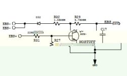
The controller board has pads marked EBS+, that apply the ebrake when the signal to them is switched from normally grounded to +5V to +12Vand they also have pads marked EBS- that work in the opposite sense and apply the ebrake when the signal to them goes to ground. Here's the circuit in the controller (with thanks to the member who originally took the time to draw it out):

ebrake circuit.jpg

Jeremy
 
amberwolf said:
A possible thought: Sometimes a second magnet permanently placed near the switch, with just the right polarity compared to the first magnet, may bias the switch to operate the opposite way (although ti may also require changing the orientation of the first magnet and/or the reed).

I'm having trouble finding a suitable reed switch with NC contacts (aka Form B) then I found this post and a pic which demonstrates how it works http://www.instructables.com/id/Make-a-Magnetic-Reed-Switch-Work-Backwards-sort-o/
 
I think the original resistor setup should work fine for inverting the signal. 1K is probably a safe bet, but I would try something higher like 4.7k to keep the current down. Too high and it won't work anymore.
 
Back
Top