KELLY / QS MOTOR CONNECTON

martinev

10 W
Joined
Jun 24, 2022
Messages
89
hi
can someone put us right please , we have the wire diagrams for the kelly kls 7230N controller and the qs 3k hub
but its not clear to us which on the controller is a input signal voltage or a which is a output signal / voltage i also read the paperwork and one plug on the hub is a spare connections plug ,

can someone clarify the connections thanks
 
Never had a Kelly, but manual seems to make it pretty clear:
https://kellycontroller.com.ua/download/KLS-N/KellyKLS-N-UserManualV2.7.pdf

Red and black on the shell are input from the battery (and on switch). Green, yellow, blue are the output for the motor phases:
Screenshot_20221215-140527.png
Screenshot_20221215-140855.png
 
hi inanek

thanks i have all the diagrams off qs web and kellys but no clarity in -or out etc,
what about the 2 plus of 9 pins, i don,t want to appear stupid but needs must ,
i know some actually say what they are but not whether its a signal / voltage in or out,
but just want to be sure , thank you
thank you for your time

Screenshot_20221215-140527.png
 
The top two circled there are battery voltage and also on the shell. The rest are all annotated as 5V or 12V, so nothing else is battery voltage.

The only sensors are the hall sensors (motor position) and temperature. You might also consider the throttle to be a sensor as well since it's usually a hall or potentiometer.

Screenshot_20221216-201147.png

The rest is all switches, CAN bus, and some meter pin that copies the motor halls to it as output - probably for implementing a speedometer.
 
hi inanek
ok great ,
the 5v and 12v are voltage out for signals or require 5v 12v input ,
the reason i'm asking this is because my design for the wiring on our 2 bike builds ,the electrical architecture is quite complicated well i think so
as we are using 2 different ah batteries, 1 is a 72v 55ah the reserve battery is a 72v 20ah each battery is selectable by rotary switch,
so i am creating to systems with different size controllers for the relevant battery size,
but these 2 systems are totally independent from each other, and only one system at a time will have a battery supply
( manually selectable which one, 55 ah or 22 ah )
so there is all the wires to the hub that have to be change over as each system is energized, this is done with a latching 24pin e-switch ,( you push it once for one controllers wires to connect to the hub press again and it change over to the other controllers small wires ( not the phase wires they are change over with a rotary manual switch) I've sorted the switching batteries
i've got sorted switching phase wires, its the small 9 pin plugs i need to sort out next .

i probably haven't explained or described it well, but please feel free if you asked me a question about my system i could answer it , or maybe it would show me i have missed something
but when its complete i will do a video,, so it the 12 small wires i need to know what's what input or output or what's not needed etc
 
thanks
here are some photos of the 1969 the vespa swing arm i designed and fabricated
then painted, the lambretta version is a different shape. Martoni is me :thumb:
:thumb:
 

Attachments

  • IMG_20221118_105413.jpg
    IMG_20221118_105413.jpg
    2.6 MB · Views: 231
  • IMG_20221118_105419.jpg
    IMG_20221118_105419.jpg
    2.5 MB · Views: 231
  • IMG_20221118_105402.jpg
    IMG_20221118_105402.jpg
    1.6 MB · Views: 231
Seems like a lot of effort having two different controllers. If both batteries support enough continuous discharge amps for normal usage, I'd just stick them in a y harnesses with an ideal diode (a MOSFET controlled by logic to work like a diode based on voltage measurements of the batteries so that you don't get the voltage drop and heating associated with plain diodes in front of each battery) like this:
https://a.aliexpress.com/_mOkESn8

And then use a single controller. No switches or dials at all that way.

If one battery supports less continuous discharge than needed normally, and so needs a different max current set on the controller, I'd try connecting the ECO switch and see if that brings you down to the reduced current needed:
> (22) ECO: Low speed switch function. Blue

Then just switch the ECO switch on whenever you switch to whichever battery doesn't support the continuous discharge needed for normal operation.

Although personally I use a CycleAnalyst display that decides the throttle signal that gets sent to the controller. The throttle plugs into the display instead of the controller. So I can just have different presets I bump up and down using the MFSwitch on my handlebars if I need to demand less from a battery.
 
Wow that's over my head. Ok well yes we was worried about the discharge differences. we only wanted the smaller battery fitted and use only as a definite reserve power source when the main battery is flat (reserve fuel tank).
That's the only reason for 2 different batteries and 2 controllers etc. and space limitations or we would of used 2 batteries the same ah.. Great info thank you maybe will look further at the options we definitely want the second battery as a just to get you home reserve. Maybe I could pay you to look at our options and configure our system.. Maybe? Thanks
 
One of the other Kelly threads does confirm the ECO switch cuts the current use in half:
dan974 said:
you can plug the economy button for 50% power, usefull in technical tracks...
So theoretically you can still have the 90A max battery current setting your controller tops out at normally and turning on the ECO switch would get you down to being compatible with a weaker 45A continuous discharge battery. Or you could use their programming app from https://kellycontroller.com/support/ to set a different max current. You'd use double whatever your weaker battery can handle if using the ECO switch strategy. Or exactly what the weaker battery can handle for a no switch option that just doesn't use the stronger battery full force, but won't be too much for either battery alone.

It supports multiple speeds as well with configurable max speeds, but not sure halving that wouldn't still try to draw too much from the battery during acceleration in the lower speed setting.

If you want to pay for buying and shipping an extra Kelly controller over to my place in California, happy to wire it up to my ebike and confirm a 30A programmed max current setting doesn't force one of my 20A max continuous discharge batteries to shut off when the ECO switch is connected. 👍
 
ref kelly kls, and QS hub
on the diagrams what are inputs to the kls
and which are the outputs from the kls and the kls plug wiring

( I've marked off in red what i think is a input signal to the kelly
marked in green i think is what the a output signal from the kelly etc

example
can some please confirm what is either a
input from a component /switch or throttle /hub
and what is a output to a component / switch or hub

and on the plug diagram i have attached
can someone mark what is a input in red and out in green please
i am totally confused after looking at the QS hub plugs and the kelly plugS for over 2 hours
thank you anyone
 

Attachments

  • kelly kls.png
    kelly kls.png
    424.6 KB · Views: 167
  • kelly kls 1.png
    kelly kls 1.png
    425.3 KB · Views: 167
Hall sensors in the motor are inputs for the controller that tell it the position of the motor's internals. It isn't output from the controller in the bottom right. Just the 5V is output from the controller to the hall sensors to power the sensor.
 
Also there is only one source of electrical power in the system and that's the battery. The battery is then only connected to the controller and the ignition switch. The ignition switch only connects to the battery and controller.

That means everywhere 12V and 5V is being provided it's the controller converting it from the battery power and providing it to the component:
Screenshot_20221222-220307.png
 
Hi inanek
thank you so much, i hope you and your family have a great christmas
and a happy new year, at least that's clarified a bit more info i can continue,
thanks again
 
hi inanek
and anyone else reading this post,
Happy new year to you all, :wink: :wink:
i have a question to you guys, we are on the way to start wiring in the 2 controllers and the
change over switches 2 x rotary switches for 2 battery system
as the batteries are different ah 55ah and 20ah but the same voltage ( and no they will not be linked in parallel )
2 totally separate systems 2 controllers and 2 batteries, see above posts,

what i need help with is i need to set up and wire in one system first, 55ah battery,
do i need the hub temp sensor,
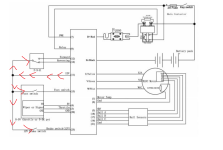
the problem i have it i have got to swap over input signals and output signals to and from the hub and switches from one controller to the other controller, or maybe there are ones i can keep shared with no ill affects to the isolated controller
i have a load rotary switch in place that
will switch over the output cables from one controller or the othe rone and send down to the hub,
so its all the smaller wires angin i have a 12 pin change over switch for these , ie throttle wires , temp sensor , power input, ground etc, but i am thinking there maybe some wires i dont need and some that would be able to stay linked to each other and not worry about back feeding for its sister controller that can stay shared, by the way which wire /pin is the clutch or brake cut out (both controllers are kelly kls )
this would to save me connecting these to the change over switch, , that can stay shared with no fear of either controller sending signals etc back out to the unused controller ( which will not have any power to it when its not been selected by the main rotary switch,,, i am very so sorry if i have made this sound complicated ,

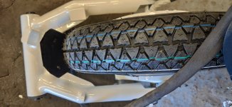
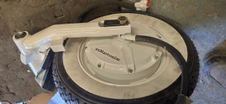
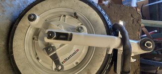
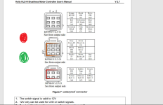
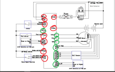
ps The picture i attached
am i right in reading the current path to this diagram
so the red arrows are the 12v out from the controller to the relevant devices ?
thanks
basically 2 wiring looms 2 controllers i need to switch from one controller to the other including switching all the needed wires .

thank you :thumb:
 

Attachments

  • 1. kls7230N.png
    1. kls7230N.png
    244.7 KB · Views: 74
thanks
here are some photos of the 1969 the vespa swing arm i designed and fabricated
then painted, the lambretta version is a different shape. Martoni is me :thumb:
:thumb:
do you have the sizes of the metal you are using in the swingarm...love the round stock use..
 
Back
Top