Raider said:
It should.
I have seen on the older light pcb's it used to be an old school resistor. Of course, that didn't prevent the familiar smoke, but I have read here in another thread that in stead of replacing that resistor, just solder straight over it. And that was supposed to give about 500mA.
Not sure if I would take the chance, though. since it takes for ever to get new controllers and snow is soon to be found here..
Anyway, now I have tried every relay I could get my hands on, and the same happends every darn time.. Resistor starts to overheat. Even with a relay with guaranteed 0 resistance and supposed to be a 250v relay..
So, I'll be cutting it out'a there all together.
Another thing I also thought about.. If the lights are connected to the controller, it is a good chance that you'll have no lights at all if you run out of juice and have to pedal.
With my bike, I can still have the battery power on and as long as I don't use the assist, I'll be able to keep lights on for at least a bit longer.
Still needs to use relays, though. If I can find a source in the controller that can manage to turn a relay on.
But the worst thing of all are still all the cables and wires on the bike. And no good place to hide it.
Mind you, I have a home brew with a normal MTB as the starting point.
Hello.
I encountered the exact same problem as you gentlemen and I think I have a simple solution
to it which is housed in the controller housing.
So far I'm after testing and everything seems to work great, as long as we have this little working PCB. :wink:
The solution is based on the use of a mosfet, a small prototype board and 3 resistors to make a voltage divider.
Thanks to the use of a mosfet taken from the old controller, I can now pass quite a large amperage through the line of lights.
The elements needed are:
IRF1010E mosfet (I just had one)
2 x 100k resistor
1x 91k resistor
PCB prototype board
(you can also do without the "spider", then you will save some space)
VIN - This is the voltage from the battery provided by the controller with the lights on.
(I'm using it here as a signal to turn on the mosfet)
GND - you just need to remember to use the appropriate cross-section of the wire.
Light control consists in "cutting off" the ground for the lamp, i.e. we pull up any voltage to the lamps and connect the ground to the middle leg of the mosfet.
To the right I connected the main ground wire, remembering to give a thick cable.
The best thing about it is that by applying constant voltage from the battery to the circuit and giving mass through the brake handles, you can make brake light in this way.
I am also trying to make a version with the omission of a small pcb board, but I encounter a strange problem with the "second light on".
I hope I helped and didn't dig up the topic unnecessarily.
Regards.

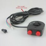
 Can any one help figure out if this circuit can hold over 100mA at peak?