Kt48zwsrkt - Controller Problem

Joined
Sep 19, 2015
Messages
10
Hello,

I wired up this new ebike controller (Kt48zwsrkt) and tested it originally was all working well.

After connecting my headlight (24v) to the switched light output started to smell something unhealthy.

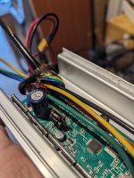
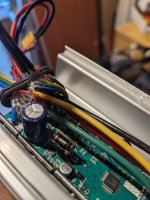
After taking apart the controller can see this fuse has blown/burnt out and the motor no longer turns. It powers up, brake sensors and pedal assist all appear to function ok. I have a thumb throttle and when using this it will make the motor "shunt" then nothing.

My questions are: Have I completely fried this controller now somehow by connecting a headlamp?

Can I find a replacement fuse and attempt a re-solder or is the whole board lost?

Would anyone happen to know what the fuse is there as it is totally burnt out so cant see any markings.

Any help/support would be greatly appreciated as on a very modest budget.

Thanks,
Alex
PXL_20231204_135717303.jpgPXL_20231204_135708701.jpg
 
By "It powers up, brake sensors and pedal assist all appear to function ok. " does this mean that you get indications on the display screen that each is working? Or was there a test you performed on each (if so, what was the test?).

By "I have a thumb throttle and when using this it will make the motor "shunt" then nothing." what do you mean exactly by "shunt"? Shunt normally means to bypass something, and isn't usually applicable to a motor or motor operation, so it's not clear what the problem you're having with it is.


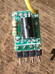
The burned / discolored device Is not a fuse, but rather a resistor used to drop the battery voltage down to the input limit of the board (which may be part of the LVPS regulator, or part of the light switching board). It would overheat and burn like that if:

--too much current was drawn thru the board
or
--too high a voltage battery was used on the system, putting too high a load on that resistor. (more than the 13s or 14s 48v or 52v battery the controller was meant for).

If the board is the LVPS:

The LVPS turns battery voltage into 5v to run the controller brain (MCU) and motor halls, throttle, PAS, etc. It gets battery voltage from the keyswitch/lock wire that comes from the display. The battery voltage to the display comes from another wire that goes back to the B+ input to the controller itself.

The display has a tiny electronic switch in it that connects the two whenever it is turned on. That switch can't take much current either, so whatever overloads the resistor can easily overload that switch. So the resistor itself might still work even though it's toasty-looking, and even be the correct resistance (you can measure it with a multmeter on Ohms), but the switch might be blown inside the display if the controller didn't power on.


Since the controller powers on and the system does operate, even if not correctly, then both the switch and the resistor are working, as is the LVPS.

So the board is more likely to be just for switching the light, and shouldn't affect the operation of the controller. If it's blown and *is* affecting it, you shoudl be able to just remove it from the controller, and while it won't have a light switching fucntion the rest would still work.

What voltage do you read at the battery positive wires (the one into the controller, and the one out of the controller to the display, and from display back to controller), and at each of the 5v wires to the PAS, throttle, and motor halls?
 
The KT controller lighting circuit is only able to supply 70mA for the lights. It’s really only of any use to power a relay and the relay output should power the lights via the battery. I used it for a while for my headlight, but was never very comfortable using it. So I fitted a dc to dc converter and a separate light switch.

You may have been lucky and not killed the controller. Here is an explanation of what is mounted on that piggy back board. You have blown the 51 ohm resistor.

 
Last edited:
Thanks for that link. This is the info on the board, in case the linked info goes away. Note that one post in that thread actually links back here to ES, where this info came from, so I've included that all below:

I'd guess that in this case the overload on the board from the probably-too-high-power-light caused damge on that board that is feeding back into the MCU or 5v supply via P1 or P2 (see below) and keeping the MCU from working correctly. Disconnecting the board from the controller would verify this, if so.

If it doesn't change anything, it means something in the controller was damaged, either in an unrelated problem or the light board problem damaged either 5v or MCU, or damaged the display B+ switch transistor so it can't pass enough current to the controller to operate the controller's LVPS (5v, 12v, etc).


Quote of post below:​


Here is the lights module as promised. The black wire from the black lights connector goes to ground.


The large transistor is a 2SA1013 and the small transistor appears to be a 2SC1815.
This is the schematic. The pins are numbered from left to right looking at the front side with the components.


The circuit is fairly simple. The part I'm not certain about is P1. It seems to be some sort of feedback pin so the micro knows the transistors are working.

These are the connections on the main board:
P1: Microcontroller pin
P2: 5V control
P3: Battery voltage from display connector (only on when controller is enabled)
P4: Ground

When the lights board is installed and the lights are enabled P2 is at 3.35V and P1 is 5.7V (seems high as it's directly connected to the micro).
 
Thanks for both your detailed responses - I really appreciate the support.

Does this mean that you get indications on the display screen that each is working? - Yes the display is indicating this. I haven't done any other tests (yet)

what do you mean exactly by "shunt"? - Apologies I understand used the wrong terminology. What I mean is that the wheel hub motor does turn a very small amount and thus "shunts" pushes the bike forward by an inch or two.

Regarding this statement:
--too much current was drawn thru the board - I used an LED headlamp that said it was 6v - 60v. I can't see any indication of how many amps it draws (AliExpress special)
1701770736661.png

--too high a voltage battery was used on the system, putting too high a load on that resistor. (more than the 13s or 14s 48v or 52v battery the controller was meant for).
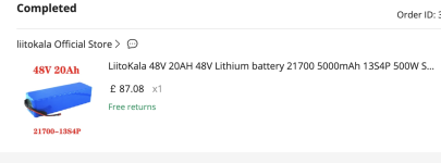
The battery 13s4p 20Ah. I believe this is OK.
1701770815121.png

The switching feature works on the display and from putting a multimeter across the output when off I get nothing and when switch on i get voltage. Now the voltage does fluctuate quite a lot from 11v - 16v - 27v - 32v I have no idea why.

When you say this: " you should be able to just remove it from the controller" - Is it a "simple" as de-soldering that part from the board?

DO you think it would be best for me to de-solder the board or attempt to solder a new 51 Ohm resistor on? I am not too concerned about have the light switch feature on the controller. Eventually I will probably get a DC-DC converter (any suggestions?) and separate switch as suggested. (Wish I did in the first place now!).

Thanks again for the advice/guidance.
 
Back
Top