LegStrong - Open-Source HW/SW controller (FOC + Bluetooth)

machado88 said:
How does your SMD FETs handle heat dissipation? Should I think on some SMD solutions for the transistors or continue on the TO-220? I don't really know much about heat dissipation in SMDs.
Haven't had any issues, just put grids of vias and heatsink underneath. They have lower inductance, in theory you can reduce switching losses using powerful drivers to switch rapidly. There's also SMD GaN fets, switching losses are so low on those that it's possible to run 100khz PWM which often means you can replace electrolytic caps with ceramic caps. Size and heat lost from capacitors is dramatically reduced.
 
lizardmech said:
I was thinking more of cases where you want to run 150-300V at around 100-150 amps. There's a lot of interesting motor designs around that aren't used in ebikes much because the controllers aren't good enough such as coreless axial flux and some inrunners with extreme ERPM values. Once you have a controller capable of high PWM frequency, higher voltage limits and very accurate current sense many new motor topology become possible to use.

Tesla seems to use resistive current sense on their inverter they just cut a busbar and weld a small piece of metal between them. I have never been able to find a picture of which IC they use though, only pictures of the shunt.

For most vehicles, 150-300v @150a seems like a lot of power, and it is, but at low RPM, if you limit to 150A your starting torque will suffer immensely, and you need very precise control over this powerful starting torque. Hall effect sensors are the way to go, unless, like TESLA you can braze some steel between your copper busbars and use that as a shunt.

High ERPM motors have terrible efficiency at high powers because of hysteresis losses and eddy current losses.

lizardmech said:
Haven't had any issues, just put grids of vias and heatsink underneath. They have lower inductance, in theory you can reduce switching losses using powerful drivers to switch rapidly. There's also SMD GaN fets, switching losses are so low on those that it's possible to run 100khz PWM which often means you can replace electrolytic caps with ceramic caps. Size and heat lost from capacitors is dramatically reduced.


GaN FETs are terrible for this application because they have higher ohmic resistance, so will have much higher losses, and are far more expensive, the money you spend on GaN FETs could be put into better gate drivers for lower switching losses.

Ceramic caps are nice, but the role you describe isn't the role that electrolytics play in a motor controller, they are there to minimise the effect of lead inductance from your battery pack, reducing the voltage transients on components in the controller.

As for cooling high power SMD FETs, like the infineon IPT059N15N3ATMA1 or IPB036N12N3, using a MCPCB/IMS is an excellent solution, allowing you to directly attach the pcb to a heatsink.
 
Most of that is not really the case anymore. Coreless axial flux motors operate at high ERPM, require high PWM speeds and reach 98% efficiency. There's many other motor topology with similar functions like this https://hobbyking.com/en_us/turnigy-typhoon-ferrous-loss-free-helicopter-motor-800kv-600-50-size-heli.html

They main issue is the lack of controllers able to handle their requirements. Coreless axial motors are very interesting as they can be printed on PCBs or made DIY very easily. Capacitors are a huge issue on low inductance motors, you need many right next to the fets to suppress voltage ripple. Simulations on capacitor effects on VESC designs often resulted in capacitors producing more heat than the conductive losses in the mosfets. Although you still need an electrolytic near the cable, high switching speeds combined with low ESR ceramic caps gives a huge advantage in power density and efficiency.

GaNfet price and resistance is rapidly falling while silicon remains much the same. For example https://www.digikey.com/product-detail/en/epc/EPC2033/917-1131-1-ND/5431627
 
lizardmech said:
Most of that is not really the case anymore. Coreless axial flux motors operate at high ERPM, require high PWM speeds and reach 98% efficiency. There's many other motor topology with similar functions like this https://hobbyking.com/en_us/turnigy-typhoon-ferrous-loss-free-helicopter-motor-800kv-600-50-size-heli.html
It is true, coreless motors have near 0 hysteresis loss because of the air "core", however, eddy current losses at high powers are huge because of the high commutation speed, unless wound with litz wire, which is overall less efficient because insulation between strands reduces packing density of copper.
Motors that have have rotating housings, similar to the turnigy you have linked do have near 0 inductive/eddy current loss to the housing, however they still have quite high losses in the laminations.

lizardmech said:
They main issue is the lack of controllers able to handle their requirements. Coreless axial motors are very interesting as they can be printed on PCBs or made DIY very easily. Capacitors are a huge issue on low inductance motors, you need many right next to the fets to suppress voltage ripple. Simulations on capacitor effects on VESC designs often resulted in capacitors producing more heat than the conductive losses in the mosfets. Although you still need an electrolytic near the cable, high switching speeds combined with low ESR ceramic caps gives a huge advantage in power density and efficiency.
All this is about coreless motors is true, but completely non-applicable in this area of operation because of power handling limits.
Ceramic caps are not the solution though because their capacitance vs volume is so tiny, that even though they have very low ESR and ESL, the energy in the voltage ripple is low enough impedance that the capacitance isn't sufficient, and even more so, to get the required capacitance at a decent operating voltage, you are looking at VERY VERY expensive capacitors, that is why in the industry we use film capacitors, for their high voltage, high capacitance (relative to ceramic) and low ESR/ESL (relative to electrolytic). However, while film capacitors are excellent, they are very expensive and not as capacitance dense as electrolytic, so we pair them with electrolytics for the best of both worlds, only using a minimal amount of ceramics.

lizardmech said:
GaN fet price and resistance is rapidly falling while silicon remains much the same. For example https://www.digikey.com/product-detail/en/epc/EPC2033/917-1131-1-ND/5431627
Yes, it is true that price and resistance of GaN FET is falling, it does not mean they are valid design choices yet - or for at least 10 years if progress continues at its current rate.
The example you linked may have a much lower resistance (still much higher than silicon fets in the price range) than most GaN FETs but its packaging makes it very difficult to heatsink, leading to its far lower current rating that other comparable resistance fets, and unsuitable for vibration prone environments, like that of an electric vehicle.
Additionally, GaN devices are far more fragile than silicon devices, incredibly sensitive to over voltage, on both the gate and the drain/source terminals, leading to much more expensive drive and snubbing circuitry.
 
About firmware,

Don't know if you will go with F3 or F4. For F3 I just found some code for FOC which may radically increase the speed to make the firmware: https://github.com/451506709/esc/tree/master/src/esc
 
I don't know where I could help. Though I am very interested in this project. Once upon a time I received my BSEE, it is what we did before there were software degrees. I wrote software most of my adult life, hinging around internet applications; but then, mostly libraries for data access from DBMS's. However, I am motivated, have a lot of time to play with, I have some experience with microcontrollers (PIC, Basic Stamp, Arduino, Raspberry Pi, etc...), I have a residency at a pretty good makerspace, and years of production and machining experience. I will be following the thread, please let me know if I can be of any assistance. Even if it is just cleaning up or organizing code. I am in the process of building an AWD reverse delta trike with a GVWR of 900 lbs. I am aiming at a Cd somewhere around 0.15, such as a light weight miniature Schlörwagen. My goal is a for a long term touring machine.

I happened across your thread investigating open source controllers, it's a passion of mine, open source that is, ever since 1993. This situation was brought about by the fact that I may need to build my own motors. If I have to go that far, what is one step further. LOL Either way, good luck to you!

---
Thank you,
Jim
 
Hi everyone,

After some time doing other stuff, I'm coming back slowly to the new controller.
But not all time was lost, I've being doing some bug correction in code and experimenting some other ports in the current controller. By the way, do never copy my use of PicoBlade connections for the cables input/output, they are too small for bumpy use.

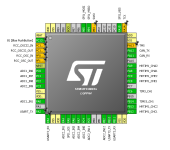
I already have the STM dev board for the STM32F334 and currently I'm trying to map the pins and do some HAL for the firmware. More on that soon (I hope).
stm_mapping.png

I've also upload some video with the current version to demo the basics. I'm running with a battery pack 14s2p LG MJ1 18650 and a Bafang motor SWX-02 350W (rated). The input is only via PAS-Sensor.
I'm testing for 15A and 18A trough this video, changing the configs on the fly (literally). I have to put some temperature readings on the controller, but for now the case do not even gets warm (ambient > 30ºC).

[youtube]HpnT7h7fUU8[/youtube]

The gauges that I'm using is just an example of an infinity of possibilities that I can configure. I still have PIDs with some issues (wheel speed, motor load, battery resistance and mileage), but the important ones are very precise.

Notes:
- The power delivery is very smooth, blended with the cadence and speed;
- Voltage drop looks fine for such a battery pack
- No Field weaking is being applied, so it is very efficient while running at ~45km/h
- Since the torque application is smooth, I feel that the motor can handle even more.
 
Nice video, good to understand how that mobile app works and the potential. That is new for me.

On my OpenSource firmware for Kunteng/BMSBAttery controllers, I will need to implement PAS code and I think I will look at your code to learn more about PAS firmware as I never implemented such thing.

For throttle, if you are interested, you can read the Throttle Control Modes notes I took from the forum: seems really valuable for throttle firmware: https://opensourceebikefirmware.bitbucket.io/Motor_control--Throttle_Control_Modes.html
 
JimFritzMI said:
I don't know where I could help. Though I am very interested in this project. Once upon a time I received my BSEE, it is what we did before there were software degrees. I wrote software most of my adult life, hinging around internet applications; but then, mostly libraries for data access from DBMS's. However, I am motivated, have a lot of time to play with, I have some experience with microcontrollers (PIC, Basic Stamp, Arduino, Raspberry Pi, etc...), I have a residency at a pretty good makerspace, and years of production and machining experience. I will be following the thread, please let me know if I can be of any assistance. Even if it is just cleaning up or organizing code. I am in the process of building an AWD reverse delta trike with a GVWR of 900 lbs. I am aiming at a Cd somewhere around 0.15, such as a light weight miniature Schlörwagen. My goal is a for a long term touring machine.

I happened across your thread investigating open source controllers, it's a passion of mine, open source that is, ever since 1993. This situation was brought about by the fact that I may need to build my own motors. If I have to go that far, what is one step further. LOL Either way, good luck to you!

---
Thank you,
Jim
Hi Jim,
for now I'm here to support anyone that wants to replicate this controller and take new ideas for the next phase.

In the next PCB I think will be easier for programmers. For now it needs some wires and a special debug tool.

Code related, I think it needs not only organization, but also some optimization, especially in the OBD/ELM327 protocol side. Basically the message framework is too dummy at the moment.
But I have no idea if it is understandable from someone looking from outside. I really have to invest some time in wiki/documentation.
 
casainho said:
Nice video, good to understand how that mobile app works and the potential. That is new for me.

On my OpenSource firmware for Kunteng/BMSBAttery controllers, I will need to implement PAS code and I think I will look at your code to learn more about PAS firmware as I never implemented such thing.

For throttle, if you are interested, you can read the Throttle Control Modes notes I took from the forum: seems really valuable for throttle firmware: https://opensourceebikefirmware.bitbucket.io/Motor_control--Throttle_Control_Modes.html

Hi casainho,

For the PAS sensor, you basically need some interruption or time counter to read the signals and count the RPM. Look for cadence.h/cpp, it is really simple.
I've also read the direction, to zeroed the cadence/torque output when I pedal in the wrong direction.

For the input power I take on this and feed the input of the torque controller with a second order equation:
IqRef_pu = ( 1 - ( 237 * ( cadence::gVars.kRPM - 0.110) * (cadence::gVars.kRPM - 0.110) ) );
Them I limit the max and zero output just to be sure.

This will give a very natural curve.
Something like 80% power when normal riding. 100% when you take your ass off. And close to zero when you are being lazy (cadence < 50rpm).
Even with a lot of power available, makes you work out a bit.

Them I have some other curves when I want to be more lazy.
I even implemented a boost function, where if you hit the RUN button, it will start a 60s timer and give you max. torque every time you go over 20 rpm.
 
Hi Felipe.

I just found a cheap chinese controller (that BMSBAttery sells) and that uses the famous STM32F103*, does FOC and have LCD/UART/Bluetooth -- please see here my notes: https://opensourceebikefirmware.bitbucket.io/Controllers--Lishui_motor_controllers.html

This controller is not so popular as the Kunteng controllers with STM8, maybe due to the smaller higher price... still, BMSBattery sells it as also some european online shops.
 
Back
Top