Max amps on a lipo calculation & motor 3 phase wire melt...

scoot-e

100 W
Joined
Aug 11, 2014
Messages
170
2 part question:

1) I bought 60 pcs 2500mah Samsung 25R 18650 cells and put them into a 12s5p config.
I am told a safe continuous max is about 3c
So let me know if this math is correct:
To get 35a max draw on batts (what the motor seems to safely be able to handle - it's a small brushless gearless hub motor 10" tire)
2.5ah x 5p = 12.5ah x 2.8c = 35a
So I'm just under 3c at 35a pull correct?

2) The only issue I seem to have when I push the motor to 40a for more than a few seconds (like a 30 second+ ride up a steep hill) is that the three phase wires start to melt through the insulation because they heat up so much, primarily within the 6-10" closest to where they exit the hub motor and they touch and short of course which effectively grinds the motor to a halt and it makes noises if you try to accelerate. They are not permanently fused at the metal, just touching because of the melted insulation, so when I separate them and re-cover with fresh insulation/heat shrink/electrical tape the motor is good to go again. I am wondering if the gauge of the wire (which looks like 14 or even maybe higher, kinda thin) were to be enlarged at the hub or the wires were shortened to the controller (they are about 15" long from motor to controller currently) or a thicker/stronger insulation were used if the motor could handle the higher amperage for a period of time? (Controller is good for up to 72v and 50a) Other than that the controller, throttle, wiring, batts all seem fine and the motor just gets a little hot to the touch but again only after a long sustained hill ride...

Help - thx!
 
Are you sure you have the right phase/hall combination? Cuz it takes quite a bit of heat to melt insulation, and normally you don't get that kind of heat unless something is wrong.

What battery current draw does your system have with no load on the wheel at full throttle?
 
1) Yes

2) That's a serious problem, and can easily blow your MOSFETs in the controller. You can shorten the phase wires to where they exit the hub and run thicker gauge wires to the controller. Or upgrade all the phase wiring back as far as the windings since it sounds like you need to replace the phase wires anyway or at the very least check they're not melted inside the hub.
Or limit your amps, but that's no fun.
And use decent connectors, since poor connections can be a major source of heat.
Also check phase combo as AW suggested.

Good luck, sounds like you are maxing out that motor!
 
amberwolf said:
Are you sure you have the right phase/hall combination? Cuz it takes quite a bit of heat to melt insulation, and normally you don't get that kind of heat unless something is wrong.

What battery current draw does your system have with no load on the wheel at full throttle?


Yes, definitely correct, and have run it for months now no prob - only issue is when I overpump the current as I said and the insulation gets hot to the touch or melts on those wires only (not the hall sensor wires etc)

If I lift the back end (with motor) in the air and full throttle it it gets a few amps max with no load I believe.
 
Gregory said:
1) Yes

2) That's a serious problem, and can easily blow your MOSFETs in the controller. You can shorten the phase wires to where they exit the hub and run thicker gauge wires to the controller. Or upgrade all the phase wiring back as far as the windings since it sounds like you need to replace the phase wires anyway or at the very least check they're not melted inside the hub.
Or limit your amps, but that's no fun.
And use decent connectors, since poor connections can be a major source of heat.
Also check phase combo as AW suggested.

Good luck, sounds like you are maxing out that motor!


1) Thx!

2) Yes, I see, but the controller is just a little warm when I go over 35amps and is rated to handle it and has never had a problem so far.

I will try shortening the run of the phase wires but not sure how to run thicker gauge wire without opening the motor (a pain but I could do it with some friends tools if necessary) - they're not melted inside because the insulation only melted in the middle of the wiring away from the hub and actually I was using 45a anderson connectors and they melted together (the plastic only) one time too so maybe it's the connection to the controller? But the controller side wiring was just fine and only the motor anderson connector side melted...

Def maxing out the motor for short periods but it's been strong...just don't know why it's melting the wires where they connect to the controller and not at the hub outlet itself and not on the controller side...
 
Could be a poor connection, high resistance, so that heat from the connectors is feeding back up the wires and heating them up. Especially if the crimp or other connection at the motor side is not very good.

If the controller wires are significantly thicker than the motor wires, they'll dissipate the heat on their side easier than the motor ones and migth not melt before the mtoor ones do.
 
I melted Andersons once when one of the connectors wasn't seated properly, quite common unfortunately and easy enough to do. Plenty of threads on ES about it. They need to be able to twist slightly, be fully seated etc but I still like them. Bullets are popular because they are a bit more fool proof.

If you aren't keen to open up the motor, the easiest option may be to shorten the motor wires and upgrade to 12AWG back to the controller, and see if that helps.

Thicker wires sink heat away from connectors very well - may be why your controller APP didn't melt?

No load current 1A to <2A should mean phase combo is OK.

edit - beaten by AW
 
thx all

Will try bullets, see if I can switch out thicker wire as well

Do you think adding thicker wire like as a coil around the existing wires with solder points to hold them together and then recovering with insulation and better /bullet style stiff connectors (if I can't get back to their source solder points) would help heat sink and resolve the issue? At least enough to get a few more amps out of the motor without the melting issue with the motor leads? 40a would be awesome and I don't go over 30-35a currently...
 
scoot-e said:
2 part question:

1) I bought 60 pcs 2500mah Samsung 25R 18650 cells and put them into a 12s5p config.
I am told a safe continuous max is about 3c
So let me know if this math is correct:
To get 35a max draw on batts (what the motor seems to safely be able to handle - it's a small brushless gearless hub motor 10" tire)
2.5ah x 5p = 12.5ah x 2.8c = 35a
So I'm just under 3c at 35a pull correct?

Hi, someone lied to you. Samsung 25R are 8C continuous cells, and even more in peaks.
 
Yes, I know the specs of the 25R's and they are posted widely online, but every post I've read says riding regularly at over 3c can severely shorten the battery cycle life and increase internal resistance which I'd like to avoid, plus I don't need more than 3c for my application...thx
 
Just curious, how do you limit the battery amps to 40A when your controller is capable of 50A?

The 9C motors Justin tested could take more amps without getting into saturation than they could without heating up very quickly. So, although you might feel a linear torque response, you may also simply be exceeding your motor's capacity to shed heat. The weak link may be the type of insulation on the phase wires, but if you change to a more heat tolerant wire insulation you may still be really close to letting the magic smoke out of your motor.

A temperature sensor seems like it would be prudent for your application.
 
scoot-e said:
it's a small brushless gearless hub motor 10" tire...
scoot-e said:
...the gauge of the wire (which looks like 14 or even maybe higher, kinda thin)...
scoot-e said:
I was using 45a anderson connectors and they melted together (the plastic only) one time too ... But the controller side wiring was just fine and only the motor anderson connector side melted...
This motor is in a tiny wheel so it's a heck of a fast wind (scooter hub) - low turns and low resistance so capable of massive current draw.

Remember that the "35A" you are mentioning is battery current NOT phase current which can be significantly higher when the motor is under load and limiting. Phase current of 90A would not be entirely unexpected - more than enough to scare the heck out of your tiny 14 gauge phase wires. See the ebikes.ca simulator for many examples - examine Mtr vs Battery Amps at low speeds and full throttle (left side of peak in red motor power curve).

The fact that you are melting phase connectors and phase wiring (only under load when the controller is (battery current) limiting and phase currents can be high) may suggest that your controller phase current is set too aggressively for your wiring. Because you call out: "controller is good for up to 72v and 50a", I'm thinking the controller may be a retrofit and the original motor controller may have had more conservative phase current limits more appropriate for the motor wire gauge. Turning down the phase current limit will take away some of your low/mid range torque (acceleration or hill climbing), but the top end on the flat will be the same.

EDIT:
  • scoot-e said:
    just don't know why it's melting the wires where they connect to the controller and not at the hub outlet itself...
    Probably because the axle is wicking away heat - even a short distance from the outlet. A few inches away out of reach of the heatsink effect, the heat builds temperature and the insulation melts.
Anyhow - just a thought.... :)
 
gogo said:
Just curious, how do you limit the battery amps to 40A when your controller is capable of 50A?

The 9C motors Justin tested could take more amps without getting into saturation than they could without heating up very quickly. So, although you might feel a linear torque response, you may also simply be exceeding your motor's capacity to shed heat. The weak link may be the type of insulation on the phase wires, but if you change to a more heat tolerant wire insulation you may still be really close to letting the magic smoke out of your motor.

A temperature sensor seems like it would be prudent for your application.


I use a separate circuit board to limit my amps and speed - actually controller can handle even more than 50a but it's at least 50a so it's not the problem for sure

Not sure how you better insulate wires, please share...but from what I've heard from others and local ebike stores it's the poor anderson connections, I'm switching to shorter wires on batts/controller and motor and using thicker 6mm bullet connections all around and that should def solve it. I realize I had way too long a leads on my batteries as I ran them long so I could keep them outside my scooter frame for easy testing/swapping temporarily but the longer run was definitely cutting power as fresh batts would get about 5mph less than before, among other reasons - I have come to believe it's the long wires and bad anderson connections...will know shortly
 
teklektik said:
scoot-e said:
it's a small brushless gearless hub motor 10" tire...
scoot-e said:
...the gauge of the wire (which looks like 14 or even maybe higher, kinda thin)...
scoot-e said:
I was using 45a anderson connectors and they melted together (the plastic only) one time too ... But the controller side wiring was just fine and only the motor anderson connector side melted...
This motor is in a tiny wheel so it's a heck of a fast wind (scooter hub) - low turns and low resistance so capable of massive current draw.

Remember that the "35A" you are mentioning is battery current NOT phase current which can be significantly higher when the motor is under load and limiting. Phase current of 90A would not be entirely unexpected - more than enough to scare the heck out of your tiny 14 gauge phase wires. See the ebikes.ca simulator for many examples - examine Mtr vs Battery Amps at low speeds and full throttle (left side of peak in red motor power curve).


Ok - that's interesting but not sure how to only limit phase current vs overall total current...

The fact that you are melting phase connectors and phase wiring (only under load when the controller is (battery current) limiting and phase currents can be high) may suggest that your controller phase current is set too aggressively for your wiring. Because you call out: "controller is good for up to 72v and 50a", I'm thinking the controller may be a retrofit and the original motor controller may have had more conservative phase current limits more appropriate for the motor wire gauge. Turning down the phase current limit will take away some of your low/mid range torque (acceleration or hill climbing), but the top end on the flat will be the same.

For the record, the only thing melting is the plastic anderson connector housing and some of the insulation on the motor phase wire side of the connection to the controller. And the controller never came with any of the other electronics and was originally built with many fets and for high power so it wasn't limited or changed in any way. Don't know how to change the "phase" current vs regular or overall current, please advise or detail more...
I def don't care about top speed as 20-25mph is plenty fast on this little thing for most city applications but the hills and higher amps are what I'm after - although as I said, 35a is what I get now and just want 40a peaks without melting so I'm not far off...

EDIT:
  • scoot-e said:
    just don't know why it's melting the wires where they connect to the controller and not at the hub outlet itself...
    Probably because the axle is wicking away heat - even a short distance from the outlet. A few inches away out of reach of the heatsink effect, the heat builds temperature and the insulation melts.
Anyhow - just a thought.... :)
 
scoot-e said:
Ok - that's interesting but not sure how to only limit phase current vs overall total current...
It's either preset in the controller or programmable via a console or special connector. You haven't provided any controller info so we don't know what you have.

scoot-e said:
For the record, the only thing melting is the plastic anderson connector housing and some of the insulation on the motor phase wire side of the connection to the controller.
yes - you already said that, although you didn't really connect the two in any way giving the impression they were not adjacent. If the insulation is melting adjacent to the Andersons, then it's from heat from a poor connection in the APPs that is wicking into the wire. If it's further away (which was my impression), then it's likely because of high phase currents and small wire gauge.

scoot-e said:
And the controller never came with any of the other electronics and was originally built with many fets and for high power so it wasn't limited or changed in any way.
All controllers are limited internally. Your controller seems to have a pretty high battery current rating so the possible phase currents are going to be very large. I don't understand the "originally built with many FETs" remark. If this was originally a big controller and someone simply removed FETs from the board, then the original internal battery/phase limiting is likely still in effect - which could be quite high. Simply removing FETs won't change that and other external limiting boards may not affect phase current at all. We don't have any notion of whether this is the intended controller for this motor or not - which may be the issue.
 
teklektik said:
scoot-e said:
Ok - that's interesting but not sure how to only limit phase current vs overall total current...
It's either preset in the controller or programmable via a console or special connector. You haven't provided any controller info so we don't know what you have.

I have a Lyen 9fet controller unmodified. Yes I know how to limit the amperage but it doesn't specify phase vs other, it's simply amp output period

scoot-e said:
For the record, the only thing melting is the plastic anderson connector housing and some of the insulation on the motor phase wire side of the connection to the controller.
yes - you already said that, although you didn't really connect the two in any way giving the impression they were not adjacent. If the insulation is melting adjacent to the Andersons, then it's from heat from a poor connection in the APPs that is wicking into the wire. If it's further away (which was my impression), then it's likely because of high phase currents and small wire gauge.

I said it again because someone mentioned that the wires were melting, which didn't happen, just the insulation
It is the andersons and then about 6 inches of insulation leading towards the motor (and all the motor wire actually but not as hot as near the anderson connection (but oddly only the motor side of the andersons melted, not the controller side in the controller to motor anderson connection)

scoot-e said:
And the controller never came with any of the other electronics and was originally built with many fets and for high power so it wasn't limited or changed in any way.
All controllers are limited internally. Your controller seems to have a pretty high battery current rating so the possible phase currents are going to be very large. I don't understand the "originally built with many FETs" remark. If this was originally a big controller and someone simply removed FETs from the board, then the original internal battery/phase limiting is likely still in effect - which could be quite high. Simply removing FETs won't change that and other external limiting boards may not affect phase current at all. We don't have any notion of whether this is the intended controller for this motor or not - which may be the issue.

Yes, my point was the controller can handle well more than I am using in terms of current and it has many fets which I mentioned because someone suggested the controller may not be strong enough to handle the current but that is definitely not the case (I have 2 of them and neither has had any problems when swapping them just to compare.)
 
scoot-e said:
I have a Lyen 9fet controller unmodified. Yes I know how to limit the amperage but it doesn't specify phase vs other, it's simply amp output period
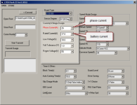
We are talking about these two fields:

  • LyenMK2.png
scoot-e said:
I said it again because someone mentioned that the wires were melting, which didn't happen, just the insulation
A euphemism - like in the thread title....

scoot-e said:
It is the andersons and then about 6 inches of insulation leading towards the motor (and all the motor wire actually but not as hot as near the anderson connection (but oddly only the motor side of the andersons melted, not the controller side in the controller to motor anderson connection)
This detail points to the connectors as the likely culprit.
The controller just has better insulation material than the motor...
Hope you get it sorted. :)
 
teklektik said:
scoot-e said:
I have a Lyen 9fet controller unmodified. Yes I know how to limit the amperage but it doesn't specify phase vs other, it's simply amp output period
We are talking about these two fields:


Ok - So should they be rated the same, say, if I want to hit 40a max, should I set them both at 40a or 45a (my separate circuit board allows me to set the max so putting the controller rating a little higher won't matter as the circuit board will limit it to 40a)?

scoot-e said:
I said it again because someone mentioned that the wires were melting, which didn't happen, just the insulation
A euphemism - like in the thread title....

I mispoke when I wrote the title that's why I tried to make it clear several times in my thread.

scoot-e said:
It is the andersons and then about 6 inches of insulation leading towards the motor (and all the motor wire actually but not as hot as near the anderson connection (but oddly only the motor side of the andersons melted, not the controller side in the controller to motor anderson connection)
This detail points to the connectors as the likely culprit.
The controller just has better insulation material than the motor...
Hope you get it sorted. :)

Thx should have an answer later today to report one way or the other
If shortening the wires and using new larger bullet connections on everything doesn't fix it then I'm afraid it's just the motor maxing out but I will also look into the phase vs battery amp rating settings for the controller - just don't have a pc so it's a little tricky to change the settings immediately...
 
scoot-e said:
...just don't have a pc so it's a little tricky to change the settings immediately...
"if Muhammad doesn't come to the mountain..."
It's awkward when doing tuning iterations, but since the controller must be powered down to flash it anyway, you can always just take your spare controller to a PC....
 
No, I mean I don't own a pc, only a mac so dont have access imediately to change the settings easily but will work on it

But what rating do I change the phase current and the battery current settings to? The same? Or one higher than the other or?
I want to reach 40a so I would assume I put it around 45a for each or?...
Thx
 
I meant that you could take the controller to work or a friend's house....

Depending on the age of the controller it may have doubled shunts, etc. Lyen can help with that. This affects the needed program settings substantially.

Generally, you want the phase currents to be somewhere in the 1.5 - 2.5 x the battery current depending on the motor, etc. so starting at 2:1 may be good (e.g. 35A rated and 70A phase). Increasing the ratio increases the phase current and yields more low/mid range torque - and more wire/controller heating. Someone with more experience with a similar motor setup may offer better guidance.

You indicated that you knew how to set the current so I'm a little confused - unless you were using some other gadget to limit current. This controller and flash program do not allow you to read the present settings so you need to get your ducks in a row for ALL the settings before you start - Lyen can tell you what the baseline is and point you to some doc he has. Best to leave your spare controller untouched for comparison should matters go awry.
 
teklektik said:
I meant that you could take the controller to work or a friend's house....

Depending on the age of the controller it may have doubled shunts, etc. Lyen can help with that. This affects the needed program settings substantially.

Generally, you want the phase currents to be somewhere in the 1.5 - 2.5 x the battery current depending on the motor, etc. so starting at 2:1 may be good (e.g. 35A rated and 70A phase). Increasing the ratio increases the phase current and yields more low/mid range torque - and more wire/controller heating. Someone with more experience with a similar motor setup may offer better guidance.

You indicated that you knew how to set the current so I'm a little confused - unless you were using some other gadget to limit current. This controller and flash program do not allow you to read the present settings so you need to get your ducks in a row for ALL the settings before you start - Lyen can tell you what the baseline is and point you to some doc he has. Best to leave your spare controller untouched for comparison should matters go awry.

I see thx, will talk to Lyen about it more before adjusting the settings
I was using the Cycle Analyst v3 to route all wiring through before going to controller so I am adjusting the overall current on the CA (the controller was preset by Lyen but have to double check the max for phase and batt amps he preset) - not sure how that would all interplay...
 
Back
Top