Value of DD Motor Phase Wire Upgrade: Winding Comparison, Field Weakening, and Motor Simulator Questions

vanturion

100 W
Joined
May 11, 2020
Messages
121
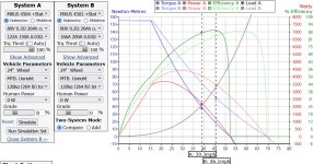
Problem: I currently have a MXUS 3K 4T motor, and I would like it to perform more like a 3T motor now that neither my battery nor my controller are limiting factors in performance. Particularly, I'd like to increase my torque above 25 MPH, exactly where the 4T under performs in comparison to the 3T winding, as well as my top speed going up hills.
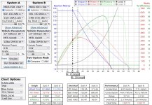
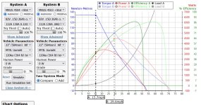
mxus_compare_1.jpg

Keeping voltage and wheel diameter constant in the simulator, as I increase phase amps on the 4T, I only get more torque where I don't really care as much about it, at low RPM and over a decreasing range as phase amps goes higher. Since the motor simulator does not simulate field weakening, some questions:
mxus_compare_3.jpg

1. Is the estimated red line a somewhat accurate trendline representation of what is happening with power requirements as the field weakening current increases and motor speed/RPM approaches 45 MPH?

2. Is the simulated torque curve above 39.3 MPH still accurate using field weakening, meaning that it would be about 20 Nm at 45 MPH for the 4T winding? Or does field weakening also change wheel torque at these (over)speeds deviating from the torque trendline plotted?

3. Lastly, is the ~52 MPH shown at 0 Nm the theoretical maximum RPM achievable by this motor winding arrangement and does it also define the max limit of field weakening?

My current layman's understanding of field weakening is that while it increases RPM, it doesn't increase torque before or after the max RPM without FW so it wouldn't help me with torque over 25 MPH, nor would it help much or any in hill climbs. This leaves me with 3 options as far as I can tell if I want to stick with this ~20 lb motor design.

A) Phase wire upgrade
B) Rewinding 4T motor
C) Buy another MXUS with 3T winding.

So rewinding doesn't look fun and I'm not too keen on buying another motor, looking at option A:

Just to run the figures on a phase wire upgrade for the 4T, I'm assuming the current phase wires are ~11AWG and the length of the wires replaced is 2 feet. 11AWG resistance is 1.26 ohm / 1000 ft, so .00252 ohms for 2 feet. I could probably fit 8AWG phase wires with teflon shrink, which for 2 feet is .00126 ohms for a difference of only .00126 ohm resistance improvement over 11AWG in each phase wire. I've read that the 4T has a .110 ohm phase winding resistance. While I'm not 100% on the calculation, I'm assuming that's between 2 windings, so 2X .00126 ohm improvement is only a 2.3% resistance improvement for performing this phase wire upgrade.

Comparing the torque at 39.3MPH between the 3T and 4T winding, you have roughly 38 Nm vs 72 Nm. If lowering the phase wire resistance only 2.3% were to proportionally increase torque of the 4T motor at 39.3 MPH, that would be a ~1 Nm improvement. This seems like a total waste of time if these calculations are correct, although a 2.3% resistance improvement would be somewhat more significant at low RPM. Am I missing something?

In other words, I got one realistic option if I want to improve torque above 25 MPH without changing the battery configuration or wheel diameter, higher KV winding motor right?
 
I would say no, no and no to your questions.

FW can increase speed and available torque above max noload speed without FW, how much depends on the motor. What you can get away with also depends on the load, thermal mass and cooling.

Some explanations here:
https://www.sciencedirect.com/topics/engineering/field-weakening-region

So.. get a good controller and try it😁
Good luck!
 
It is easy to solder thicker wire to the phase winding wires but its harder to stuff them through the axle, that is why its common for people to go to huge thick wire right after the axle exit.

For the graph it takes less and less torque to maintain the speed at the throttle position that is why the torque goes down I dont know how it would be a real world graph unless you do the trip simulator, up the battery voltage for more speed and up the battery discharge to get more torque if your controller matches it. Gearing the hub motor down with a smaller diameter rim/tire can work.
 
larsb said:
Some explanations here:
https://www.sciencedirect.com/topics/engineering/field-weakening-region

Thanks, but I wasn't able to glean too much insight from the excerpts I looked at there. I found a youtube video where the last 8-10 minutes of the lesson helped me out a good bit. I only have 1 lingering question, but more on that in a minute.

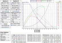
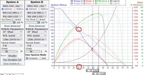
I messed around with the motor simulator some more and came up with a better direct comparison that matched the constant-torque plots for the controller settings I want to run with my 4T.

mxus_comparison_4.jpg

It's interesting how much more battery and phase amps are required to match initial performance at 100% throttle. Looking at roughly the speed where the efficiency delta between the 2 motors is greatest,

mxus_comparison_5.jpg

it's interesting how much more you have to pay in terms of energy (and heat) for that extra 30 Nm @ this instance. I know looking at this it's not ground breaking stuff for the forum, but anyway, I think I spent enough time simulating now to want to stick with what I've already got.

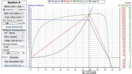
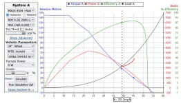
As for my remaining field weakening question, making the simulator look more like the example from the youtube lesson:

mxus_comparison_6.jpg

For this 4T motor, field weakening is only active above the no-load speed of 39.3 MPH and if that is right is it also correct to say that any speed above this achieved with FW will always produce less than 38 Nm of torque?

Last thing/correction, I noticed from the other thread that the .110 ohm winding resistance was measured right at the winding terminations and doesn't include additional resistance from the stock phase wires and connectors. This means the gains from a phase wire upgrade would be even slightly worse than I originally calculated. That said, I already have the materials on hand so I'll probably still do it sometime anyway.

One more thing, for anyone interested in making their own DIY teflon heat shrinked phase wire upgrade, here's an ebay vendor selling 10 FT increments of 175C teflon heat shrink for a very reasonable price.
 
I think this comparison might be on system data points that are not really the same. I haven’t used the simulator so much but i think if you put 100% throttle on two systems with different kV they will behave differently in the sim. Look at the acceleration data which is close to 2x difference so the comparison isn’t balanced to a point where the motors are just going steady. The power cannot be compared during acceleration, doing that does not make sense since higher acceleration must be achieved with higher power, regardless of motor.

You probably need to balance the throttle settings to meet your desired load point in equilibrium and then compare power and efficiency of the two systems. I’ve seen some comparisons before like that and the difference was small.

With your settings in the plot that would be at roughly 52mph for motor1 and then the other motor needs lower throttle so that it also meets the load at 52mph.
 
larsb said:
The power cannot be compared during acceleration, doing that does not make sense since higher acceleration must be achieved with higher power, regardless of motor.

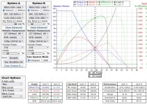
Yeah, you're right. Putting that aside, the comparisons I was making before weren't very good or accurate either because I didn't change the motor winding resistances. Fixing the estimated resistances (although I haven't measured R_batt yet) and matching max RPM of 4T to partial throttle of a 3T, it's as you say, less than a couple points difference in system efficiency:

mxus_comparison_7.jpg

I guess perhaps one of the boons of running a 4T over a 3T winding if you do a lot of accelerating at 100% throttle is generating less heat in the constant torque region as well as less heat in the constant V_batt region of the chart due to the inherent performance benefits and limits of the winding. By picking a phase amp limit to generate what I think will be a good maximum torque level and simulating just enough battery amps to fully develop that constant torque region, you can see the 3T requires quite a bit more battery and phase amps to match 4T initial performance translating into a lot of heat during acceleration:

mxus_comparison_8.jpg

Although if I didn't care to match initial performance (which I don't think I do as accelerating after 20MPH is more fun), keeping the same battery and phase limits between the motors makes the 3T winding a lot more attractive:

mxus_comparison_9.jpg

In any case, I'll keep what I have and probably run battery and phase limits around 112A and 130A to try and keep maximum system power around 7000W. With statorade, hub sinks, and possibly a phase wire upgrade, that hopefully will be enough to keep things relatively cool most of the time.

After running so many simulations now, I really get the sense that these motors aren't really all that great of a design. I can see why it seems some are moving away from DD hubs as there doesn't seem to be any effort from manufacturers to improve the design for 3KW and greater power levels in years.
 
vanturion said:
After running so many simulations now, I really get the sense that these motors aren't really all that great of a design. I can see why it seems some are moving away from DD hubs as there doesn't seem to be any effort from manufacturers to improve the design for 3KW and greater power levels in years.

QS motor video claimed 98% efficiency for one of their latest hubs so evolution is definitely still ongoing.

https://m.youtube.com/watch?v=33f-Pq9Wz34&feature=youtu.be

Better materials, better designs are still possible. I have to say that putting a 98% efficient motor on a moto or ebike is still a bit of a waste as the saving you get is minimal compared to if you switch to riding a covered vehicle with lower air resistance.
 
larsb said:
QS motor video claimed 98% efficiency for one of their latest hubs so evolution is definitely still ongoing.

https://m.youtube.com/watch?v=33f-Pq9Wz34&feature=youtu.be

Better materials, better designs are still possible. I have to say that putting a 98% efficient motor on a moto or ebike is still a bit of a waste as the saving you get is minimal compared to if you switch to riding a covered vehicle with lower air resistance.

Interesting, but QS seems pretty heavily scooter/motorcycle oriented. I know the QS205 has been pretty popular and do well with higher performance, but still a bit heavier motor than I'd like to run since I'm putting it onto a bike rack sometimes and it's already a pig even without the batteries attached.

I get what you're saying regarding aero, but I just really like the convenience of the bicycle format. Most of the time I like pedaling and cruising along at 16-22 mph, but I also like to ride my bike with traffic on 40+ MPH roads to get to those nice low traffic areas and bike paths where I can go back to low-stress cruising. Then there are other times when I've been known to use the bike to "time-attack" a really twisty road or 2. It's nice to be able to do both. It's a super niche market, so I get why a manufacturer hasn't made the ultimate low-weight, high-power 0-45MPH capable hub motor.

Anyway, can't really complain, just running what I have is already pretty capable and fun. This is one of those times where I think it's better to just be happy with what I got since I'm not planning on attempting to design my own motor. I started this thread mainly to to see if there was anything that could be done to improve the torque capability at mid-to-high RPM without changing max V or gearing and the answer is pretty much no. Ah well.
 
Back
Top