
You are using an out of date browser. It may not display this or other websites correctly.
You should upgrade or use an alternative browser.
You should upgrade or use an alternative browser.
Miles' 90mm inrunner build thread
- Thread starter Miles
- Start date

liveforphysics
100 TW
From my understanding of it, it makes no difference where the copper is located on the tooth with respect to the flux produced in the tooth, if it's in that slot somewhere, the flux lines are totally contained and all channeled up to the hammer of the tooth.
This motor sounds like it will have some outstanding efficiency my friend! I love how small you've manged to get your loss components.
That's absolutely the path to optimizing a system, look at your losses, understand where the come from and the relationships that effect them, then try to do everything you can to minimize the effects that cause them.
I'm personally into nit-picking how do anything possible to reduce a motors full RPM no-load power. Making a bad-ass motor is like a game where your goal is to have it capable of as much torque production as possible while still having the smallest possible full-speed no-load power. If you can do that, efficiency and high performance and everything else just falls into place on it's own.
*Edit* Wow!!! Just got to see your amazing 10,000th post my friend, and it's breath-takingly sexy copper-fill prawn! If you can achieve that wind shown (and I know if anyone can do it, you can), that motor is going to be so amazingly capable and efficient and cool running! Your copper loss component is going to be so small it's insignificant. You will have a motor that not only cruises at 1kW with possibily never-before-seen motor efficiency on an ebike, but also will have some serious current headroom if you decide to have an "off-road-only" power setting on the controller.")
This would be the perfect low-inductance ultra low conduction loss power stage to match your motor. Add a few caps and drive it with a lebowski BEMF matching sensorless brain.
http://ixapps.ixys.com/DataSheet/MTI200WX75GD.pdf
This motor sounds like it will have some outstanding efficiency my friend! I love how small you've manged to get your loss components.
That's absolutely the path to optimizing a system, look at your losses, understand where the come from and the relationships that effect them, then try to do everything you can to minimize the effects that cause them.
I'm personally into nit-picking how do anything possible to reduce a motors full RPM no-load power. Making a bad-ass motor is like a game where your goal is to have it capable of as much torque production as possible while still having the smallest possible full-speed no-load power. If you can do that, efficiency and high performance and everything else just falls into place on it's own.
*Edit* Wow!!! Just got to see your amazing 10,000th post my friend, and it's breath-takingly sexy copper-fill prawn! If you can achieve that wind shown (and I know if anyone can do it, you can), that motor is going to be so amazingly capable and efficient and cool running! Your copper loss component is going to be so small it's insignificant. You will have a motor that not only cruises at 1kW with possibily never-before-seen motor efficiency on an ebike, but also will have some serious current headroom if you decide to have an "off-road-only" power setting on the controller.
This would be the perfect low-inductance ultra low conduction loss power stage to match your motor. Add a few caps and drive it with a lebowski BEMF matching sensorless brain.
http://ixapps.ixys.com/DataSheet/MTI200WX75GD.pdf
Thanks Luke!
Thanks for the link. I am hoping to use the Lebowski "brain". It would be great to have a complete Endless Sphere system.
You're right. There's no "silver bullet" solution. The way to get a reasonable motor seems to be to optimise every single factor you possibly can. Going over the process again and again....
10,000?...quantity AND quality...well done, sir.

Farfle
100 kW
I was hoping the 10,000th post would have some aluminum stock and bearings in it 
Revised comparisonMiles 90mm Inrunner
Wt 1.15kg
Km 0.49 Nm/√W
Specific Km 0.43 (Nm/√W)/kg
Joby JM1S
Wt 1.8kg
Km 0.83 Nm/√W
Specific Km 0.46 (Nm/√W)/kg
Miles 90mm Inrunner
Wt 1.15kg
Km 0.62 Nm/√W
Specific Km 0.54 (Nm/√W)/kg
Joby JM1S
Wt 1.8kg
Km 0.83 Nm/√W
Specific Km 0.46 (Nm/√W)/kg
We'll see...........
Ah, IC. I thought that perhaps you calculated it by dividing the torque with the square root of the losses (total or copper). I remember that we discussed a way to have a number a for the no load losses. But I haven't followed that thread in a long time.
It would be great if we could factor in the parasitic losses......bearing said:I remember that we discussed a way to have a number a for the no load losses.
speedmd
10 MW
From my understanding of it, it makes no difference where the copper is located on the tooth with respect to the flux produced in the tooth, if it's in that slot somewhere, the flux lines are totally contained and all channeled up to the hammer of the tooth.
Hi LFP
Agree miles has done a outstanding job with the optimization. I see now how permeable the core is and how well it carries the flux. Interesting stuff.
Have you got any references for that, speedmd? It's news to me. I was more worried about the fact that the more distant from the core, the greater the endturn length.....speedmd said:It is my understanding that you want as much copper as possible up as close as you can get to the iron.
liveforphysics
100 TW
SpeedMD- I think someone gave you bad info my friend. It's about amp-turns in the slot, and where they happen to be in the slot or how many layers are above or or below makes no difference in the field on that tooth where it counts.
liveforphysics
100 TW
Miles- From a quick estimation, if you run a >97% efficient belt drive system as I assume you will, and make a controller with the new IXYS 6x 1.1mOhm RdsOn 3phase leg drive chip (your controller will be >99% efficient at 1kW), your single largest loss component in your vehicle from wall outlet to tire is likely to be charger efficiency and the voltage sag on your battery.
If charger and battery are selected carefully, you'll have a decent shot at being ~90% efficient in energy transfer from wall to tire. That may be a first in DIY EV history.
If charger and battery are selected carefully, you'll have a decent shot at being ~90% efficient in energy transfer from wall to tire. That may be a first in DIY EV history.
speedmd
10 MW
According to all the formulas I find so far, radius (distance from the iron) of the loop is key. I do not profess to be a expert by any stretch, but just trying to get to the root factors here.

Yes more amps and more wraps will be stronger, but we are talking what is the best way to wrap rectangular wire. Having seen the insides of some very exotic motors and how they wound them, has me questioning this.
Yes more amps and more wraps will be stronger, but we are talking what is the best way to wrap rectangular wire. Having seen the insides of some very exotic motors and how they wound them, has me questioning this.
speedmd
10 MW

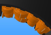
EDIT! I have gone through the posts the best I can. Agree it is misleading. The pop up caption on the page make it much clearer what it is that I failed to see originally. It is of two separate coils in a transformer application and not motor related.
liveforphysics
100 TW
speedmd said:Image of coil current flow analysis.
Im not believing that is a calc of current density. Possibly flux density or thermal mapping, but current density in a coil should be very uniform in a coil with approximately uniform x-section.
speedmd
10 MW
Hi LFP
Paragraph above image talked about current balance analysis not thermal. Could be anything. Still looking. http://www.comsol.com/products/4.3b/
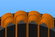
The super high performing stuff I have seen was almost always wound like this which has me thinking.

Paragraph above image talked about current balance analysis not thermal. Could be anything. Still looking. http://www.comsol.com/products/4.3b/
The super high performing stuff I have seen was almost always wound like this which has me thinking.
speedmd said:Image of coil current flow analysis.
What are the dimensions, and what is the frequency?
That looks like current distribution in a coil with high enough frequency current flow.
speedmd
10 MW
Have no clue. They (comsol) are showing the software. We need a electromagnet specialist to help steer the boat. I am just shoveling coal
Edit; I edited to original image post to reflect that it is not motor related.
Edit; I edited to original image post to reflect that it is not motor related.
Similar threads
- Replies
- 7
- Views
- 584
- Replies
- 36
- Views
- 2,386