liveforphysics
100 TW
Beautifully done my friend. ")
When are you ordering lams?
When are you ordering lams?
Quite soon, now. I might order the wire first, just to be sure....liveforphysics said:When are you ordering lams?
Miles said:Quite soon, now. I might order the wire first, just to be sure....liveforphysics said:When are you ordering lams?
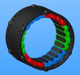
Latest revision:Miles 90mm Inrunner
Wt 1.15kg
Km 0.62 Nm/√W
Specific Km 0.54 (Nm/√W)/kg
Joby JM1S
Wt 1.8kg
Km 0.83 Nm/√W
Specific Km 0.46 (Nm/√W)/kg
It would be possible to have a mechanical switch for the fans. A latch could be moved by an actuator rod in the hollow axle....liveforphysics said:Those fans look extremely potent IMHO. You may find your no-load increases substantially driving them, but at least if anything is gonna raise no-load, you would want it to be cooling.
Miles said:Thanks speedmd. I've been using 3D CAD, of one sort or another, for 14 years, now. I'd recommend that you get a 3D controller such as the Space Navigator from the start.
I'm looking forward to learning about the practical aspects of motor building now. The winding is going to be a challenge.......
Get a deburring wheel. Cheers.Miles said:4t winding gives better cooling but, obviously, lower inductance (0.04537 mH at peak Eta). Hope that's not going to be problematic...
Nothing I've read suggests that the proximity of the coil to the core has any significant effect on the flux produced by it.Wheazel said:A question:
Does it matter on some motorparameter how tight the winding turns around a statortooth?
And by that i mean compared to the theoretical scenario when the wire would wrap around the statorteeth with no radius, thus making the total wire slightly shorter.
I get that the resistance will be marginally higher from a slightlylonger wire but I am wondering if it affects the motor in some more ways?
Thanks bearing.bearing said:Miles said:4t winding gives better cooling but, obviously, lower inductance (0.04537 mH at peak Eta). Hope that's not going to be problematic...
If you intend to run proportionally lower battery voltage to reach the same speed, it's not going to be problematic at all, since everything stays the same, in proportion.
If you wind it with one turn, and get 3uH, it's still a non issue, if you drive it with a proportionally lower voltage.
You can not only look at the inductance number. You have to put it in the perspective of the voltage and current. If your motor had 1A peak current, 45 uH would be a disaster, but if it had 1000A peak current, the PWM-frequency would be smoothed out to where you couldn't even notice any ripple. And perhaps, 45uH would create too much phase lag to even reach peak efficiency at higher speeds, unless you increase battery voltage.
I think that a properly designed (iron based) motor (like yours) can never have too low inductance. It's only if you make the teeth too thin which makes them almost saturated by the magnets (which I think the case is with the colossus and maybe other RC-based motors). And perhaps if you have some strange proportions like very big diameter and very short stator.
Nothing I've read suggests that the proximity of the coil to the core has any significant effect on the flux produced by it.
Miles said:Thanks bearing.
I was concerned because some controllers seem to have an absolute minimum inductance limit?
Eg. Accelerated Systems give a minimum inductance figure of 100uH (0.1mH)
Miles said:Hi speedmd,
Fill factor is important because of the correlation to Rm. I guess the thermal significance of "packing" depends on whether the motor is vented, or not?
Here's a good paper. I must have posted it before, somewhere....?

Rm is directly proportional to the fill-factor (inversely!). You need the greatest aggregate conductive cross-sectional area possible, for the chosen number of turns.speedmd said:Still not seeing the Rm relationship to fill factor/ eddy current losses.
) Then it struck me that the value given in Emetor is probably for the induction of a single phase (I checked this with Stephan). So, to get the phase to phase induction figure, I'd need to double this............ This is for a wye termanated motor. Is that estimate with the coils in the magnetic field?Miles said:I woke up yesterday morning worrying about the inductance of my motor (as one does...
90uH is a bit closer to 100uH than 45uH was...