Miles ZX40ST refurb project

That's fair enough, didn't realize it was for AC as well and all you have to do is plug it in.
The point that always strikes me is overall efficiency: fuel to heat to electricity through grid, charger and battery to heat again vs. Fuel to heat...
Keep us updated, hope you have it on the road soon!
 
Had a slow couple of weeks on the truck due to our youngest having her high school graduation party, but I'm back in the saddle.

Last week I managed to drive the truck for just a couple miles, fulfilling my goal of having the truck move under its own power before June ended. With an 83 Volt battery, top speed was only 45 or 50 mph, but I found later that I was only getting to about 2/3 throttle before running out of pedal travel. This has been corrected now. The truck is also now insured and plated, so drive testing can now begin in earnest. I will be testing at both ~80 Volts and ~155 Volts to try to figure out if I'm better off living with high current for the whole system, or high-ish voltage for the motor. If I'm lucky, my reversing contactor will arrive today or tomorrow (I realized that building one from multiple regular contactors was not such a good idea after all.) Here's hoping for a productive holiday weekend!
 
Well, I guess it was time for a real snag....during drive testing yesterday at 155 Volts, the coupler for the driveshaft broke:


The splined piece had to be retrieved from the side of the road. The breakage dropped the front end of the driveshaft onto the pavement at around 60 mph. Remarkably, the shaft survived with only a bit of road rash to the front connector:


The problem appears to have been that the adapter was not quite perfectly straight with relation to the motor shaft. This caused (what seemed like) light vibration, and the strain caused was apparently greater than I thought. Guess I should have shimmed things until they were closer to perfect before driving at speed. The coupler lasted for about 25 miles of road testing yesterday. So now I need to revisit this design and see how it might be improved. Hardened steel might be a good first step. I'll definitely be more diligent about getting better positioning with whatever goes there next. Taking suggestions......

On the plus side, I was able to determine that I definitely want to run the truck at 155 Volts. At 85 Volts, top speed was not quite what I wanted (adjusting the throttle for full travel made no difference at all) and the truck felt underpowered, especially at low speeds. At 155 Volts, power was MUCH easier and smoother. Towing and heavy loads will be handled with much greater ease than they would be at 85 V. Sparking seen at the commutator was pretty light, but I was being very careful to accelerate gently at all times. Sparking only occurred under heavier acceleration, but I never got anywhere near the acceleration potential of the system before the breakage occurred. I'll be pulling the motor back out to advance the brush timing 5 degrees or so. I'm now confident that this will be just fine for reverse...I just have to go slow when moving backward. Switching in some additional series resistance with the accelerator while in reverse should make it perfectly safe, even if the foot slips.

So...next I need to figure out what I'm using for the main charger. Open to suggestions here too. Documentation of many chargers out there is pretty spotty so far as I can tell--not always easy to tell if a given charger will work, or how hard it may be to get it set up just the way you would need it.

Still plenty to do for the weekend, but I sure wish I could drive some more today....
 
I seem to remember that if you have a single-piece driveshaft between the transmission and the rear-end differential...they need to be at slightly odd angles. Sounds crazy (wouldn't perfectly straight be better?), but that might be an issue to research. I am no expert at this...

ujoint_driveshaft_angle_alignment.jpg
 
Good input guys....but no cigar, I think. I had put in a call to my dad before my last post, but he didn't get back to me until after I posted. I think we have figured out the problem, which I'll spell out in a minute.

Spinningmags, the driveshaft angles were good. It looked like the first pic in your post. Max tilt of the shaft at full suspension travel should not exceed 7 degrees. My dad and I found a max deflection of 5 degrees, so that should be golden.

When I was showing my dad the concept for using the output shaft of the Miles tranny to the original driveshaft, he noted that the slop in the splines where these two pieces interfaced seemed excessive. I initially brushed this concern aside, reasoning that it wasn't a problem on the stock truck, so why should I worry about it now? Well, the additional damping provided by the oil seal at the original trans/driveshaft interface must have been important, OR the off-throttle load presented to the shaft by the AC motor (or ICE) means this slop doesn't really matter. The worst vibration in the truck occurred when taking the foot off the accelerator, during the first couple seconds of slowdown. I now believe this was caused by the DC motor shaft splines hammering back and forth between the driveshaft splines during this time. Gently applying the brake would settle it down. It would likely not have made any difference if the shaft adapter had been perfectly straight. These splines must fit tighter, or disaster ensues. My mission now is to go to a junkyard and find a suitable correlating pair of parts from a vehicle with good-fitting splines, then have the coupler rebuilt and driveshaft reworked.

Dnmun, my brother had suggested the two-piece driveshaft as a possible solution, but after talking this through with my dad, I'm sold on the idea that the spline fit must be fixed. Maybe we should keep chewing on the two-piece concept as well.
 
let the guys who are driveline specialists decide. they know this stuff and will have the best opinion of how your failure was provoked.

if you go to a two piece driveline then you can go to the junkyard armed with a tape measure to find the parts that would allow the intermediate bearings of the 2 piece fit to your frame from a junkyard small pickup.

those guys may even know from experience where to look and which trucks to look for.
 
It's been a slow and frustrating couple of weeks. I've been collecting a lot of opinions on the driveline issues and realizing I have significant work to do yet. Picked up a dial indicator and will taking a hard look at the stuff that attaches to the motor shaft. I need to pull the motor again anyway to advance the brush timing a bit, this will also be a good opportunity to get runout measurements of the motor shaft and try to rethink the coupling method--a shorter output assembly would help.

I got the reversing contactor mounted to the truck and have the coils wired up to the fwd/rev switch on the console. The original interlocks on the 12V system have been ravaged pretty bad and reconstructing all that is a tedious task, but things are moving forward.

I'm playing with a couple ideas for placement of the motor controller. The Raptor is a capable box, but it's largish--too tall to go in the original controller location under the passenger seat. It also must be kept dry. The bulk and dryness requirements make finding a suitable location a bit of a challenge. I've narrowed the choices to two possibilities:
1) Under the hood. It's tight, but it's otherwise empty real estate for the most part. Tight up against the passenger side works OK, but keeping things really dry there will require some effort. There's ample opportunity for water entry around the headlight, through the grill, and other various nooks and crannies. Building a structure around the controller to repel all that water while allowing airflow will be a challenge.
2) Behind the passenger seat. I will not have high voltage out in the open anywhere in the cabin. This means an enclosure would have to contain the controller and all wires coming and going. There's room there, but the passenger seat would be limited in its rearward travel with this option. There is a vent to the outside conveniently located right there, and an aux fan could be placed there to ventilate any unintended emissions from the controller in case of a failure. Dryness is no problem, and I may even be able to recycle the heat off the controller in the wintertime. Shorter wire runs to the battery, contactor, and motor there too.

I fashioned some brackets for mounting the controller under the hood. I figured an easy way to attach them to the firewall of the truck would be to weld a couple bolts to the firewall. So I did the first one...looks good. I weld the second one....looks good...what's that smell...smoke....coming from under the dash...what the f....WARNING!! The sound deadening blanket in these vehicles is very flammable! A fire would never happen this way in a modern western car where the cardinal rule for materials-- especially in the cabin--is non-flammability. I took this for granted and it turned out to be a mistake with this Chinese-made roller. I was quickly able to determine where exactly the fire was, and it was still very small. I tried blowing it out with one puff, no dice so I grabbed the extinguisher and put it out with one quick puff. Cleaning up the extinguisher mess was really very easy--cleaning up the soot to get rid of the smell was a bigger deal, but things look OK now and the smell has just about entirely dissipated in the last couple days. Lucky for me, the fire also singed a bit of wiring harness just bad enough to make the headlights come on any time the 12V battery is connected, so I get to fix that now too....sigh...this too shall pass....and this truck WILL roll again!
 
Complex systems are... complex! I guess that's why they have teams for this kind of thing normally, since there are tons, and tons, and tons of things to consider in unison. I've known a few guys to catch the stuff on the other side of a vehicle weld on fire - interior panels, insulation, oil in the oil pan - that's a bad one. At least you were able to snuff it out in short order! If you need hasty attachment points in sheet metal with flammable or non removable backing, never forget the venerable Riv-nut and riv-stud, could come in handy.

Your coupler runout issue is a common one among conversions that I've seen, the familiar drive line vibration sound is well documented in many a conversion first drive video on YouTube. It usually takes some very careful machining to solve, or a flex coupling which is not always ideal. For your dial indicator not sure which type you got, but there are two main types - a plunger style, and a lever style - the latter is far better to use for rotating applications like checking runout in my limited experience. They come in half-thou and ten-thousandth gradations. Like this:

Dial%20Indicator_1.jpg


Splines are ok. Chinese splines - I dunno. I'd consider an adjustable pillow block bearing for the OD of your drive shaft that you could use for support, rather than trying to eliminate play in the splines. Fixed to the motor/mount, the bearing would provide a structural low runout interface for the connection point that could be lined up with the motor output shaft. The outer D.S. surface should already have low/no runout in relation to the splines, but... it's chinese - so you might need to turn a few thou on the outside - which may be necessary anyway, in order to fit an available bearing. When I say pillow block, I really mean a flange mount type - it would mount parallel to the motor face and it much easier to adjust for runout problems than a pillow block, which has mount "ears" perpendicular to the face. Oversize or slotted holes make adjustment of a flange mount type pretty damn easy.

I like the passenger compartment mount for the controller. Simplifies, probably saves weight, eliminates water proofing concerns. Your containment here is just a no-touch instead of fabricating a water/dirt ingress prevention solution under the hood, much easier. You can bend up a no touch protective "enclosure" on a sheet metal brake in a few minutes.

I was really partial to this kit 10kw/60a DIY charger that was available a few years back from a Russian guy with a business called Electric Motor Werks. I don't see the kits there anymore, but he is selling a 12kw charger and some crazy Chademo goodies, might be worth a look? There is a huge thread on DIY electric car about the charger, I didn't read it all to see the state of affairs.
 
kd8cgo,

Thanks for the excellent input and encouragement. The dial indicator is a plunger type, but it works well enough. I got up the gumption to pull the motor back out last night. I found 10 mils of runout on the base piece of the adapter that attaches directly to the motor shaft. No runout on the motor shaft itself. Turns out the hole that allows the bolt to go into the center of the motor shaft needed just a tiny bit of metal filed away so the piece could mount perfectly straight. Runout is now under 1 mil. Clearly I took too much for granted with the pieces I inherited with this project. Next round will be way better....hopefully good enough to last. I'm leaning toward the support bearing for the front end of the DS myself instead of a two piece shaft. I'll be talking to the guys who did the driveshaft in the next day or so. They have lots of DS experience and parts on hand, maybe they can supply this part as well.

Brush cover is off the motor now...will probably be advancing brush timing tonight. Feeling much better about it all today....
 
Brush timing is now advanced by about 7 degrees. Motor runs faster forward than reverse with the same input...success! Planning to swing by the driveshaft shop tomorrow.
 
I went to the driveshaft shop today to get their input on the broken adapter. Their feeling is that a pillow block supporting the front end of the driveshaft is the key to a fix. They recommended using the same tailshaft and slip yoke, stating that the fit of the splines was not unusual. So, they are fitting the slip yoke to a pillow block bearing, which they already had on hand. After I get that back, I'll have the adapter rebuilt with hardened steel and a bit more bulk (talked to the machinist earlier this week). I'll also have to fabricate a bracket for the pillow block. So, it looks like this issue is close to resolution. Fingers crossed!
 
Excellent news!

For the mount, you can use two pieces of C-channel, or rectangular tube to get the "height" offset from the motor surface for your bearing. A plate or flat bar bridging the surface gives you a location to mount your flange ears. Depending on the total height, some triangulation would need to be put into the mounting bracketry for stability. Hot roll channel or bar stock mounted in this way should give you a fairly parallel surface, but many pillow block mounts have a spherical bearing surface in the "block" part to allow for some misalignment in that plane. It even allows for enough error in that plane that you could even build a scaffold of sorts out of lighter materials with any flat top surface for the bearing to rest on, without too much trouble.

Another bracket idea I really like, is using round pipe or tube with perpendicular plate at both ends. This has the advantage of shielding the smooth yoke surface. I mention this because it would be better for keeping the slip yoke surfaces and spline lubricated and clean, which will be important to keep the rust off so it can slide as your driving.
 
You pretty much nailed it...it's as though you were one of the guys at the driveshaft shop! Thanks again for your input. I'm getting excited again about what's coming in the next couple weeks.

Are you in Motown? EDIT: Never mind, I know where you are ;)

73,
 
Well, things are not looking much better yet. I had a second motor adapter piece built, with much more bulk and strength than the first one:

We built a cross-member to mount the support bearing to, and attached it to the frame with some nut plates we fab'd up. Here it is all in place:

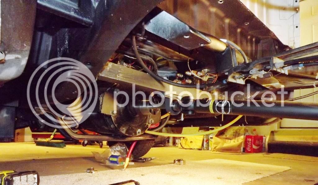
Unfortunately, this did not cure the vibration problem, and the adapter still would not stay put on the motor spindle. The three set screws were not enough. So I had 7 more set screws added to the base adapter piece. Still no dice. I can get the adapter to go on straight, but I can't get it to stay put. The truck will drive ok up to about 30 mph, but it you get much above that, it starts shaking like mad. The consensus seems to be that for the rpm's I'm after (up to about 5,000) I'll need a much better-balanced and less bulky adapter. Ideally, I need a slip yoke that will slip directly onto the motor shaft, enabling elimination of the adapter altogether.

In theory this is relatively simple....but I'm having a hell of a time finding a part that will mate to the splined shaft of the motor. The shaft has an odd size and spline pattern that does not seem to exist in the automotive or agricultural PTO worlds. I found an automotive slip yoke with the right pattern (Spicer 3-3-6701X), but it is about .1" too large in diameter. This is probably too much to take up with rubber coating or other means that I'm aware of. A suitable part may exist in the forklift world, but parts in that realm seem to be much less well-indexed, and since I don't know what kind of lift my motor came from originally, finding a mating lift part may be very difficult, but I suppose I may have to try. Even if I can find a part that mates to the shaft, it may not be something that can be fashioned into a slip yoke. I spoke with Net Gain Motors...they had nothing, and pointed me to a clutch and driveline shop in IL. They also had nothing, and pointed me to a device called the TranTorque. It's basically a high-strength compression-force shaft coupler made by a company called Fenner. Does anyone have any experience with this device? If this can't be made to work, then I'm likely down to having a custom part made, which will cost hundreds of dollars and require removal and hauling of the motor to the machine shop that makes the piece--something I'd rather not do if I can avoid it. OR, I will have to change motors to something I can mate to more easily, something else I'd rather not do at this point. This one aspect is turning into a real nightmare. Any advice is appreciated.

On the plus side, I have managed to mount the motor controller in a decent place behind the seats, and fashioned a plastic cover to keep hands off the high Voltage. The reversing contactor is in place and working. The damaged harness inside the dash has been fixed. And, the front section of the splash pan is nearly complete:

This includes a few pieces, including a rubber upper section that is riveted underneath the cabin floor. More pics are at the photobucket page. I'm trying to keep going as I can, but unless I can get this driveline issue sorted out, this will never amount to anything. Trudging on.....
 
can you verify that the output shaft of the motor or the center of the adapter is axial? is there any run out that you can measure on the end of the adapter piece when it is mounted to the end of the motor shaft?
 
dnmun said:
can you verify that the output shaft of the motor or the center of the adapter is axial? is there any run out that you can measure on the end of the adapter piece when it is mounted to the end of the motor shaft?

No runout on the shaft--it's straight. I can get the adapter on such that there is no runout in the output shaft, but there is some imbalance in the other areas of the adapter. This works OK at low speed, but once you go too fast or hit a bump, the adapter moves on the motor shaft and is then out of alignment. No number of set screws seems to be able to cure this.
 
Could you get the motor out and get it balanced somewhere with the adapter on?
One of the cars at the company I worked for got the brake disks balanced while mounted as it had a lot of vibration that couldn't be explained otherwise - smooth afterwards.
 
you found a yoke that would mate to the splines but it was 1" too large, why? where would that get you? can it be turned down on a lathe at the drive line shop?

my first instinct is to examine the higher frequency flutter type oscillations of the joint made at the contact surfaces of the splines. set up a regime to examine the magnitude and speed where the oscillations start and find a way to record it so you can collect data.

then change the grease in the spline joint. look up viscosity modulus stuff for the different greases, and test with each one of several. also heat the spline joint an equal amount for each of them and maybe repeat with higher heat. that would give variables to relate back to the structural data you will know about the grease. see if you can find a variable that changes with the speed at which this phenomena occurs.

if nothing affects the speed at which this occurs, i would go back to the splines on the motor and remove the huge moment of the force created by extending the axis of the motor. so look at the yoke and rethink the priority then, if you don't see something affect it.
 
.......pointed me to a device called the TranTorque. It's basically a high-strength compression-force shaft coupler made by a company called Fenner. Does anyone have any experience with this device? I
Yes, I have used TranTorque couplers on high torque industrial drives.
They are like a very heavy duty taper lock device (if you know what they are ,).. Generally used to lock a sprocket or gear onto a smooth shaft, But do not rely on a key way to help transmit the drive. Obviously various sizes available for shafts from around 10mm.... Up to freekin huge ! :D
I don't see how you would easily utilise one in that application, or if it would help with the vibration issue....but I am sure it could transmit the torque as reliably as any spline shaft.
http://www.fennerdrives.com/trantorque/_/Trantorque-GT-42mm/?s=ZnwxNzky
 
If I understand correctly: you cannot find a female splined piece to match your motor shaft. The part you have is slightly over-sized and doesn't stay concentric under load, causing runout/vibration/destruction?

if so, a taper-lock is what jumped to mind. Those Transtorque couplers could well do the job. I guess all you need a smooth round coupler turning up to mate the driveshaft yoke to the coupler O.D. (keyed or even welded together).
 
Punx0r said:
If I understand correctly: you cannot find a female splined piece to match your motor shaft. The part you have is slightly over-sized and doesn't stay concentric under load, causing runout/vibration/destruction?

if so, a taper-lock is what jumped to mind. Those Tran torque couplers could well do the job. I guess all you need a smooth round coupler turning up to mate the driveshaft yoke to the coupler O.D. (keyed or even welded together).


Thanks for all the great feedback everybody, it's been very helpful. After chewing on dnmun's suggestion for a while, I concocted an experiment that was both easy and effective. I took up the slop in the existing tailshaft/slip yoke combination by putting some very thin fabric over the tailshaft and forcing on the driveshaft. This eliminated all visible play in the fit. I was able to spin the motor up to a much higher speed now with no problems, but at some point either the poor balance of the assembly plus the fabric kicked in or the fabric wore through and vibration started, once again dislodging the adapter's position on the motor shaft. From this I concluded there are two simultaneous problems:

1) The spline fit at the slip yoke is too loose and is indeed a source of trouble. Ironically, adding the support bearing made the problem worse by focusing the moment of the slip yoke in such a way that it had to slap back and forth on the shaft just to rotate.

2) The existing adapter simply does not have enough shock resistance to reliably stay put

The answer is two-fold: I'm going to use a trantorque to join a new piece of shaft to the motor and have the driveshaft changed yet again. It will need to be a little longer and have a new slip yoke to mate with the new shaft. I don't believe I'll use a support bearing in the final iteration.

If you go to www.fennerdrives.com and download their catalog, you can see the specific style of bushing I'm looking at on pages 87-89, the B-Loc WK series, which is specifically for butt-joining of two shafts. The shafts can be different size, but I will be trying to have the new spline shaft at the same diameter as the motor shaft (1.355") to simplify things. With a rated torque handling of 774 ft-lbs in the size range I'm looking at, I think this device should be adequate. Please chime in if you disagree. So, Automotive Supply is hunting for parts (spline shaft and slip yoke) for me now. Once I have the new shaft piece, I'll call Fenner and tell them the dimensions I'm working with and get a recommendation on which device I should use. Wish me luck!
 
That coupling looks well-suited IMO. I like that it can be attached over existing splines and handles bending moments. It sounds ideal for your problem.
 
Back
Top