Min Voltage for Throttle Output of Cycle Analyst 2.3

Joined
Jun 12, 2013
Messages
26
Hi
I'm trying to setup my cycle analyst 2.3 for current limiting. I've wired it up and it does work but it is output 0V as a minimum voltage which is putting my Grinfineon motor controller into regen mode when I'm not on the throttle. Is there a way to set the minimum throttle output. My throttle goes from 0.86V to 3.7V. I've tried setting the Max Throttle and the AuxThreshold. Do I need to update the firmware? Can I update the firmware? Do I need to add a resistor or diode of some kind to pull up the min ThO? Seems really odd when the manual clearly says that most throttles are from 1-4V that the cycle analyst doesn't just mimic this by default.
 
(edited the below irrelevant info to really tiny print because i was an idiot and didn't read the thread title) :oops:
the defaults actually are 1v - 4v, afaik.

but the section you're looking for is in the throttle menu section, under ThrO->Min Out

https://www.ebikes.ca/product-info/cycle-analyst-3.html

SETUP THROTTLE OUT

The Cycle Analyst sends the Throttle OUT signal (ThO) to the motor controller via the CA-DP connector. It can be set up as either a variable voltage signal for ebike controllers or as a digital 1-2mS pulse for RC controllers. The min to max output range should be adjusted to correspond to the throttle input range of the controller to ensure the controller is driven to max at full operator throttle and is completely OFF when the operator throttle is closed.

Ramping options can help achieve smooth power engagement and remove the aggressive edge from powerful motor systems. When Up, Down, Fast, or PAS rate limiting are in effect a small {U,D,F,P} flag appears before the OUT voltage on the Diagnostic Screen to assist in tuning these settings.

ThrO->Outpt Mode
Selects between a steady analog voltage output on the CA Throttle Output line or a 1-2ms RC servo style pulse output. Almost all ebike and EV controllers operate off a voltage throttle signal, while the R/C pulse mode enables the CA to control compact ESCs from the hobby industry.

ThrO->Min Out
This is the voltage or pulse width sent to the controller for ZERO rider throttle. It should be about 0.2V below the actual voltage where the motor controller starts to respond. The default value of 1.0V is fine for most setups, but if the controller does not start turning the motor until 1.4 or 1.5V from the CA, then the Min Out setting could be increased to ~1.2-1.3V for a faster throttle response with less deadband.

ThrO-> Max Out
This is the voltage or pulse width sent to the controller for FULL rider throttle. Most ebike controllers will achieve full output between 3.5 to 3.9V on the throttle, and the CA3's Max Out should be at least 0.1V higher than this to achieve full power.

NOTE: Many controllers have a throttle overvoltage fault similar to ThrI->FaultThrsh. The CA3's Max Out must be lower than this controller fault or the controller will shut off at full throttle.

ThrO->Down Rate
Determines the maximum rate at which the throttle output can ramp downwards. For safety reasons you would generally leave this at a high value so that the system can shut off promptly, but there can be times where a slower disengagement of motor power is preferred. Values of 4 to 8 V/sec are recommended. Ebrakes cut power immediately and are unaffected by this setting.

ThrO->Up Rate *
Determines the maximum rate at which the throttle output can ramp upwards once current greater than FastThrsh is detected. This setting is popular for smoothing out the harsh kick on powerful systems. A lower value in V/sec will result in a longer time for the throttle to ramp up and results in a more gentle application of power. Values of 0.5 to 3 V/sec are recommended.

ThrO->PAS Rate
Determines the maximum rate at which the throttle output can ramp upwards when engaging in PAS mode. This can be used to achieve a smooth PAS power application while still allowing for a fast response with the throttle. Operation is otherwise as with UpRate.

ThrO->Fast Rate
Determines the maximum rate at which the throttle output can ramp upwards when controller current is less than FastThrsh. When current reaches FastThrsh, the rate becomes governed by UpRate or PASRate. This dual rate approach allows the Throttle output to quickly reach a level that starts having a measurable effect on the motor before then dropping to the normal Up or PAS rate limit. This eliminates time lag for a ramped throttle output to catch up with the bike when you apply the throttle and are already moving. Values of 3-8 V/sec are recommended for controllers that have an immediate response. For controllers with built-in ramping (such as eZee), or sensorless controllers that have a startup routine delay, a lower FastRate rate may be required to prevent overshoot.

ThrO->Fast Thrsh
Determines the threshold controller current at which the CA's output ramp switches from FastRate to UpRate or PASRate. This setting should be quite low for direct drive hub motors, such as 1-2A. However, for gear motors or mid-drives, the setting should be a bit higher than the no-load current required to accelerate the motor from stopped, typically 2 to 4 Amps. A value of 0A disables FastRate so only UpRate or PASRate is applied.


i recommend following the manual and/or unofficial user guide (uug) and setting up each section of the menu step by step, skipping no steps at all, until the ca does all the functions that you want it to in the way you want them to.

if you don't, you may miss some setting that interacts with another setting in a way that makes your system not behave the way you expect it to.

the throttle is one example; in the uug (and probably in the manual by now) there is a step by step process for ensuring the ca output matches your *controller's* throttle input range (not your throttle's output, as that doesnt' always match what the controller actually needs), and ensuring the ca input matches your throttle's output, so that the full range of the throttle is usable over the full range of the controller's input, with as little deadband as possible, etc.


following every step takes longer to set it all up to start with, and makes a lot of people impatient...but if followed the results will be more predictable and closer to what you are after (it almost always takes fine tuning during test rides to get it "just right").
 
I tried this https://www.ebikes.ca/product-info/cycle-analyst.html#firmware-and-programming but the CA3_Prelim6_NoCal.hex that the updater comes with doesn't seem to work. The screen goes all corrupted.
I followed this and upgrade to 2.4 https://www.ebikes.ca/news/new-ca2-firmware/
Version 2.4 doesn't seem to have any options related to the min throttle output either.
I couldn't get the V3 software to work based on this https://www.ebikes.ca/product-info/cycle-analyst-3.html#firmware-releases
 
ah, well, i guess it would have helped if i'd actually *read* your thread title. :oops: :(


with a v.2.x you don't have any actual throttle output from the ca, it only has a pulldown line that connects to your controller's throttle line via a diode.


so all it can do is drop the voltage to essentialy zero, grounding the throttle line, if you don't have the diode. with the diode, it might be limited to around 0.7v. (whatever the diode's vf forward voltage drop is).

so there are no settings for minimum throttle because it isn't adjsutable.

the v3.x firwmare can't work on the 2.x units; it's a different hardware setup. so the 2.4 is the latest stuff you can use on it.


now...in the next post i'll start over, talking about the correct hardware and stuff. :lol: :oops:
 
keep in mind that it's possible that the v2 simply always drops throttle to zero volts whenever ther'e's no input, because that would normally not be a problem for a controller--the grinfineon (and phaserunner) are exceptions, because they are designed to start proportional regen below 0.8v on throttle input.

so we have to find a way to ensure the voltage never drops taht low on your grinfineon's throttle input, regardless of what the ca does.

curtis.perrin said:
I'm trying to setup my cycle analyst 2.3 for current limiting. I've wired it up
ok. first question is:

exactly how is it wired?

are you using the "ca plug" on your grinfineon? below is the ca's own dp (ca connector); the controllers is the other version of that plug that fits into the one pictured.
dpconnection.jpg


if so, how old is the grinfineon? if it's not pretty old, then it's probably wired for the v3 ca, and needs a modification for v2 ca's.

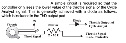
if so, then, you'll need to add a diode and resistor to the green throttle wire. it doesn't matter if this is inside the controller, or just in the cables from controller to ca connector, or in the cables from connector to ca itself. it's usually done inside the controller simply because the wires are all right there already, and the diode and resistor can then be taped up or heatshrunk safely inside the controller casing. but it can be done anywhere you have access to your throttle's signal wire, it's ground wire, and the ca's throttle override wire, all at the same area.

the diode and resistor are wired like this:
cav2 throttle wiring.png
per the cav2.3 manual page 14
https://www.ebikes.ca/documents/CycleAnalyst_V23Web.pdf

if you're not using any dp connector but are using independent hand-wiring of things, you'll have to do the same thing with that.


there is also a way to not use just an override, but to actually have the ca v2.x output a throttle signal, but i've never done that with a 2.x ca (just the 3.x), so you'd have to go to page 20 section 9.3 if you want to do that; and follow the instructions there. it requires opening up your ca and soldering stuff to the board inside....

if you're already doing it this way, then we'll have to find a circuit to do (like the one above) that will not allow the ca to drop the voltage to zero.


if it's wired some other way, please draw it up and attach the drawing to your post using the attachments tab (below the box where you type your post in)
 
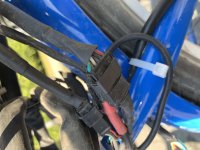
Hi I figured out my problem. The throttle lines from the cycle analyst wasn't connected (or had a bad connection which would explain the intermittent behaviour I was seeing). The retaining clip on the connector had bent up so it was being pushed out of the connector rather than making a connection. It works now!

Man that manual is confusing though. I definitley missed the fact that the Cycle Analyst had a wire already to control the throttle and that lead me to trying to use the "current throttle" Aux Voltage thing in the advanced settings. Maybe this would have been obvious if it was connected properly and had worked when I initially set a max speed.
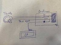
I've attached a drawing of what I think the Cycle Analyst throttle wiring actually is. Maybe the diode is in the CA but it gets the point across.
imgonline-com-ua-CompressToSize-p5Y5sHAxssyJ.jpg

The ITermMin now is essentially what I was talking about before. If you set it to 0V and then exceed the speed limit by pedalling or by going down a hill it will pull the controller into regen. So I set it to 0.8V and no problem.

Thanks for the help.

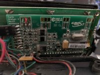
imgonline-com-ua-CompressToSize-boLkOJV1pS7872bt.jpg
imgonline-com-ua-CompressToSize-i8omJacdtIgKBb.jpg
imgonline-com-ua-CompressToSize-JWMkfB7SBkuG.jpg
 
curtis.perrin said:
Hi I figured out my problem. The throttle lines from the cycle analyst wasn't connected (or had a bad connection which would explain the intermittent behaviour I was seeing). The retaining clip on the connector had bent up so it was being pushed out of the connector rather than making a connection. It works now!
yeah...bad connections are one of the hardest things to troubleshoot...and are the majority of problems i find people to have (though until they actually find it, they don't believe it could be the problem).

Man that manual is confusing though.
i have trouble interpreting a fair bit of their documentation; they tend to leave a lot of stuff out, assuming you'll "figure it out". even for me, that doesnt' always happen without help, which is harder and harder to get directly from grin tech these days. :/


The ITermMin now is essentially what I was talking about before. If you set it to 0V and then exceed the speed limit by pedalling or by going down a hill it will pull the controller into regen. So I set it to 0.8V and no problem.
i'm glad that worked. i didn't realize itermmin was basically the same as throttle output minimum.

back when i started with ca's, i barely explored the ca v2.3/2.4 control options, used it just as monitoring. when i was trying to get it to do limiting i had too many problems because of lack of understanding of the control loops and variables, and too little explanation in the manual.... (at least, of the kind that i can absorb well).
 
Back
Top