Modular, Multi-Platform, 300A ESC

Thanks amberwolf, yes I do get email alerts to the same email address from same GH acc. from other repositories.

It may be how I have GH configured, i.e., only pull requests and such get emailed, maybe not just someone adding files to a repository.
 
Thank you @mxlemming for pointing me here. Looks interesting, still need to read up on the details, find out what bluepills, blackpills are ;) and intersted to see the schematics. Might be just what I'm looking for for my outdoor robot project, which badly needs bigger controllers:

[youtube]66sWmYbuUBI[/youtube]

EDIT: I borrowed a Flipsky 75100 to test and it works like a dream :p very nice, smooth, quiet, no cogging.
 
A-DamW said:
Well 5 of these just showed up in the mail!

Let the shenanigans begin!

Welcome to the club. Here is some additional information from the MP2 project:
  • Gathering motor parameters [LINK]
  • Pin mappings between MP2 and the F405 pill [LINK]
  • MP2 assembly, testing and firmware [LINK]
  • MP2 bus bar methods [LINK]
  • Some (not very good) examples of connecting the MP2 to a motor [LINK]

And if you create any interesting boxes please let us know and we can put them in our gallery of enclosures.
 
Thanks owhite,

I have been getting very acquainted with the MP2 github docs, nice authoring by the way.

Seems like a recent restructuring broke those links, these should work:

Gathering motor parameters https://github.com/badgineer/MP2-ESC/blob/main/docs/MOTOR_PARAM.md
MOSFET selection https://github.com/badgineer/MP2-ESC/blob/main/docs/MOSFET_PARAMETERS.md
Pin mappings between MP2 and the F405 pill https://github.com/badgineer/MP2-ESC/blob/main/docs/MP2_F405PILL_PINOUTS.md
MP2 assembly, testing and firmware https://github.com/badgineer/MP2-ESC/blob/main/docs/PCB_ASSEMBLY_TESTING.md
MP2 bus bar methods https://github.com/badgineer/MP2-ESC/blob/main/docs/HIGHER_AMP_ASSEMBLY.md
MESC Firmware on the MP2 -- getting started with STM32CubeIDE https://github.com/badgineer/MP2-ESC/blob/main/docs/FIRMWARE_INTRO.md
Some (bad) examples of connecting the MP2 to a motor https://github.com/badgineer/MP2-ESC/blob/main/docs/QS165_MP2_WIRING.md
 
mxlemming said:
There was one casualty towards the end - the black pill regulator bit the dust suddenly and with no apparent reason. I THINK it was probably because I had connected the STlink 3v3 to it as well. Nothing else was harmed as a result, I just had to pop it off and put a 78M33 regulator on the black pill pins which is... ugly but effective.

yes that was the reason, I burnt several of my Arduino pro mini boards by this way with the ST-link 4 pin connected, later on when I connect only 3, never happened again. fortunately it damages the regulator and only the regulator.

Great work anyway!
 
MP2 users might be interested in using our latest version of the F405 pill which is available at the github repo.

Features:
  • Full compatibility with the MP2 ESC, VESC firmware, and the MESC firmware systems.
  • Standard blue/black pill header arrangement (2, 20 x 0.1in headers with 0.6in spacing).
  • Kicad BOM contains links to jlcpcb for rapid PCBA.
  • Four layer design with two inner uninterrupted ground planes.
  • USB-C connector.
  • CAN pin header.
 
Hi All,
I've been following this project for a while now as I like this concept very much, today my first set arrived and I'm ready to join as a tester :)
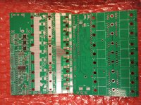
mp2.jpg
This is the way JLCPCB sent out the board, I payed some extra dollars to do hand soldering, the grand total for 5 assembled MP2 and 5 assembled F405 pills was 250USD plus shipping and taxes.
I would like to configure it with VESC. Even though I have experience with STM32 and I have an idea about how to compile VESC for MP2 it would be great if I could get some help. Which version do you use, is it compatible with 6.00 or 5.03? In 6.00 where are the HW files? Should I use hw_MP2_v0.3.h along with hw_MP2.c?Which bootloader to use? Compile it or can I use a precompiled one?

Thanks, best regards
Andrew
 
Hi All,
I've been following this project for a while now as I like this concept very much, today my first set arrived and I'm ready to join as a tester :)
View attachment 330793
This is the way JLCPCB sent out the board, I payed some extra dollars to do hand soldering, the grand total for 5 assembled MP2 and 5 assembled F405 pills was 250USD plus shipping and taxes.
I would like to configure it with VESC. Even though I have experience with STM32 and I have an idea about how to compile VESC for MP2 it would be great if I could get some help. Which version do you use, is it compatible with 6.00 or 5.03? In 6.00 where are the HW files? Should I use hw_MP2_v0.3.h along with hw_MP2.c?Which bootloader to use? Compile it or can I use a precompiled one?

Thanks, best regards
Andrew
Hi Andrew, nice looking boards. Fingers crossed for you. What MOS are you using? We're finding more and more that the MOSFETs are the most critical thing in electrical performance... Some brands are perfect some are virtually impossible to tame. Best choices we found so far are the crst030n10 and the ipp026n10.

Hardware files for VESC should be identical whether using VESC 5 or 6. Have a check of the pinouts to make sure you're matching up the VESC hardware conf with the physical pill you have... Owhite swapped some pins around to expose a much more useful io combination and I'm not sure if the hw conf has been properly tested yet (I haven't done any work on it, me Netzpfuscher and Owhite are generally using/working on MESC firmware).

If you have Linux you can compile and flash directly following BV's instructions as normal. If you're on windows, then the easiest option is to find a binary (get someone to compile for you, I might be able to at some point) and use stm32 cube programmer and the USB bootloader (if you reset the pill with the boot 0 jumper shorted it will go into bootloader mode and can be programmed with no tools).

You don't need to burn a bootloader with VESC. You burn a normal firmware image and add the bootloader through VESC tool. Same bootloader for every board.

Good luck!
Thanks for the quick answer. I will use CRST030N10, they arrived today from Aliexpress.

Ok, I will check the pinout. @owhite what is the testing status of the VESC headers, how careful do I have to be? :) I have the 1.1 version of the pill, is hw_MP2_v0.3.h compatible with it?

I already created the Linux build environment. Do you mean that I don't need to compile and upload the bootloader separately, just compile and upload the VESC firmware, and after connection upload the precompiled bootloader named "generic" from VESC Tool?

Thanks,
Andrew
Skimming through this header, there are two noteable issues...
1) the LED has been reassigned from GPIOC 12 to GPIOA 15 F405_pill/hw_MP2_v0.3.h at 27b805182f68b01741bff64052bbdbf775234211 · davidmolony/F405_pill

2) The pinout has been reassigned to break out GPIOC 10,11,12 instead of some useless things, so there is now physically SPI available on an extra header.

This does not mean it will not work, just you won't have a green LED unless you modify the header and your UART/I2C will point nowhere on your combination of the MP2 and pill...
Schematic for Pill: F405_pill/F405_pill_schematic.pdf at main · davidmolony/F405_pill

Header
I2C - set to be I2C1 on PB6/7 F405_pill/hw_MP2_v0.3.h at 27b805182f68b01741bff64052bbdbf775234211 · davidmolony/F405_pill

UART - Set to be UART 4 (SD4) on PB3/4 or UART1 on PB6/7 F405_pill/hw_MP2_v0.3.h at 27b805182f68b01741bff64052bbdbf775234211 · davidmolony/F405_pill

SPI - Set to be SPI3 on PC10/11/12 or SPI1 on PB3/4/5(NSS not really important AFAIK, but is available on PA4... which is the throttle...) F405_pill/hw_MP2_v0.3.h at 27b805182f68b01741bff64052bbdbf775234211 · davidmolony/F405_pill

With that changed... It should work. There are no changes to the critical current or voltage measurements or the BRK input (overcurrent and voltage protection).

Check you have soldered the correct jumpers on the back before adding MOSFETs and bolting it down, it gets tedious otherwise.

I have not tested the above, and won't have a chance to for a while. If you do test it, please get back to use and confirm/deny functionality/submit a pull request for the modified header!

You are correct re. bootloader.

Let's hope you got the "genuine" variety of Aliexpress CRST030N10 MOSFETs. Seems unlikely they would fake already cheap MOS but I just had a search and they are... improbably cheap.
 
Last edited:
Ok, I will check the pinout. @owhite what is the testing status of the VESC headers, how careful do I have to be? :) I have the 1.1 version of the pill, is hw_MP2_v0.3.h compatible with it?
Stick with mxlemming's answer he's the firmware expert -- I'm just a pcb layout 🐒🐵.

If you create header files and test them under VESC we would be very interested in hosting them at our site.

Also please share any suggestions you have for assembly or other relevant issues that could go into our documentation.
 
Last edited:
Stick with mxlemming's answer he's the firmware expert -- I'm just a pcb layout 🐒🐵.

If you create header files and test them under VESC we would be very interested in hosting them at our site.

Also please share any suggestions you have for assembly or other relevant issues that could go into our documentation.
it is interesting to see the 4 copper layers are:
top - 3.3V
inner 1 - GND
inner 2 - GND
bottom - 3.3V
while the general rule like this:
top - signal w/o GND
inner 1 - GND
inner 2 - PWR
bottom - signal w/o GND
just wondering if there is some good reason/lesson learnt?
 
while the general rule like this:
top - signal w/o GND
inner 1 - GND
inner 2 - PWR
bottom - signal w/o GND
just wondering if there is some good reason/lesson learnt?
I assume youre referring to the pill. I agree with the "general rule" and normally use it. The MP2 crew wanted to minimize noise on the pill as much as possible -- badgineer (who designed the MP2) read up on the subject and suggested we try the two inner ground layers. I would not say that we have tested if it makes any difference, but so far we've been very pleased with the lack of noise issues on the pill. Others among our ranks wrote off the discussion as "witchcraft". 🤷‍♂️
 
Stick with mxlemming's answer he's the firmware expert -- I'm just a pcb layout 🐒🐵.

If you create header files and test them under VESC we would be very interested in hosting them at our site.

Also please share any suggestions you have for assembly or other relevant issues that could go into our documentation.
Thanks @mxlemming and @owhite
I'll report back on the progress, I'll contribute to the GH repo. Not saying that it'll be fast, but I have plans with the MP2 so I definitely have the motivation
 
I assume youre referring to the pill. I agree with the "general rule" and normally use it. The MP2 crew wanted to minimize noise on the pill as much as possible -- badgineer (who designed the MP2) read up on the subject and suggested we try the two inner ground layers. I would not say that we have tested if it makes any difference, but so far we've been very pleased with the lack of noise issues on the pill. Others among our ranks wrote off the discussion as "witchcraft". 🤷‍♂️
Owhite and Badgineer watched this:
And decided 2 grounds were the best option.

Personally i go for 1gnd 1 power but either works...

EDIT:
In case anyone reads this in future, my rationale is as follows:
1) It is quite hard in more complex designs to add decoupling caps everywhere on every pin, they are a pain.
2) The problem with trace routing is parasitic inductance which limits di/dt and therefore makes it harder to supply the MCU pins.
3) Within a plane, moving current loops between any two points has as low an inductance as to be negligible. This is because the inductance comes from changing magnetic loop around the current carrying trace, but with a plane, the magnetic loop has to extend all the way around the edges of the plane and so it is both a very long (weak) magnetic loop and also does not change much -> very low parasitic inductance.

Very well, but what about the return path on signals?
Well, when you have a trace and you route it above a ground plane, two things happen. Firstly, the return current can flow directly under the trace, and secondly, the presence of a plane under the trace blocks/absorbs the changing magnetic field, by generating Eddie currents in the plane. So:
4) When you route a trace over a power plane, you are still blocking the changing magnetic field around that trace, and so the inductance of the trace is minimised in the same way as if it was over a power plane.
5) The return path is compromised to some extent, but the effect is far subdued below what it immediately looks like because of the presence of the power plane. The return path can take all kinds of tortuous routes within the power plane and ground plane until it finds a decoupling capacitor - and there is near zero parasitic inductance in the planes. Therefore, the power plane is nearly as effective as the ground plane in returning the signal.

This became very apparent when I was playing with single layer IMS boards. Single layer should be disastrous for a power stage. The parasitic loops are huge, like half the board in size, the ringing and switch node bounce should be enormous. But it is not. The IMS boards I made switch several hundred amps in 50ns with virtually no overshoot and ringing. On single layer FR4, this would be impossible.

The difference is that the IMS boards have a slab of aluminium 0.15mm below the copper, and this firstly completely blocks the magnetic fields and secondly can act as a return path for the parasitic flux linked through induction of current into the aluminium substrate. If the effectiveness is so visible on a 400A in 50ns switching event, the effectiveness with a piddly little 0.000xA event at a TTL logic or analog signal will be even more so.

So in summary, my more complete opinion on the matter is:
[signal+PWR]-GND-GND-signal is marginally better (which on ultra high frequency designs may be critical!) IF AND ONLY IF you are able to absolutely guarantee the decoupling of every single device on the board through localised capacitors. If you are not able to guarantee this, then foregoing a power plane will have a bigger negative impact than the benefits attained through the better signal returns.

On the MP2, overwhelmingly the biggest source of parasitic inductance and layout issue is the pill to MP2 interface, with the ~cm long pins that are 2cm from some of the signals. And yet there does not seem to be an issue related to this. People like to debate shit they have heard about and are told is a super important issue at the expense of not finding the real issues...

I am a mech eng, and the other day a softy showed me how he had tuned his PID loop using some cunning math to eliminate position errors. I tightened the bolt holding his encoder to the rail and stopped it rattling around.
 
Last edited:
Thanks @mxlemming and @owhite
I'll report back on the progress, I'll contribute to the GH repo. Not saying that it'll be fast, but I have plans with the MP2 so I definitely have the motivation
I did use my MP2 with VESC. I haven't had time to report everything here, sorry about that ...
I had to switch back from mesc to vesc because I needed datalogging before road testing and since I had already a serial to bluetooth adapter it was the easy route.

Not sure my header file could help you much nor my compiled firmware because we are probably not using the same version MP2 and F405 pill. I ordered both while development was still going fast.

But as far as I can tell not a lot of change was needed from the provided header files, I just changed those parameters on the header file :

#define VIN_BUS_R1 1000000.0
#define VIN_BUS_R2 33000.0
...
#define HW_ADC_EXT_PIN 4
...
#define HW_LIM_CURRENT_ABS 0.0, 320.0

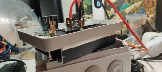
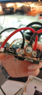
I mounted my board to a heatsink in a not so good way but it seems to work as of now (not much test have been done) :

1678133099951.jpg
1678133054641.jpg

The board is mounted on the heatsink with only four screws isolated with heatshrink and 3D printed spacers. I have used one of those isolating thermal pad between the fets and the heats sink : https://fr.aliexpress.com/item/3289..._main.362.48e75e5bBeUv21&gatewayAdapt=glo2fra

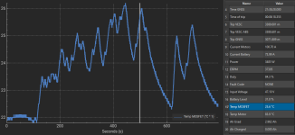
So far with my testing temps on the low side center fets haven't gone higher than 26°C ! (not a long test and only 100A and a short test at 120)

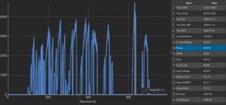
Here is on vesc log plot of power and MOS Temp :

log_vesc.PNG
log_vesc_temp.PNG

So far this is working great. Hope that I can fix all the other weak links soon to test it at higher power level !
 
I did use my MP2 with VESC. I haven't had time to report everything here, sorry about that ...
I had to switch back from mesc to vesc because I needed datalogging before road testing and since I had already a serial to bluetooth adapter it was the easy route.
...
So far this is working great. Hope that I can fix all the other weak links soon to test it at higher power level !
The tubing around your MOSFET retaining bolt is an interesting approach, and I also happen to like using thermal pads. :) I also like what I see so far of your enclosure, it looks like good progress towards a splash-proof design. Great work -- it's really nice to see your progress!
 
The first reason I had to bolt through was that I haven't put screws on before soldering all fets and didn't want to fatigue the legs nor strip pads from the PCB by bending them :p. I think heatshring passing 1mm the tab musshrom on the first thread and might hold isolation (time will tell). I mounted everything on a waterproof electrical box but it's not the best volume wise. Next one I build I will do the terminals parallel to pcb and try designing a slim waterproof enclosure.
 
the mini360 has no anti-current flow backwards function, it is better to have a diode in series to supply power to the pill. it is very convenient to flash the pill on board with battery/power supply turned off.
 
Does anyone have the HFI working? it could be the modelized design producing huge noise totally covered the signal. it is quite frustrating.

BTW, I attached the F405_pill V1.1 head file for someone who may have interest.
 

Attachments

  • hw_MP2.h
    9.4 KB · Views: 7
Back
Top