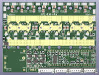
Modular, Multi-Platform, 300A ESC

Does anyone have the HFI working? it could be the modelized design producing huge noise totally covered the signal. it is quite frustrating.

BTW, I attached the F405_pill V1.1 head file for someone who may have interest.
HFI works perfectly on the mp2 (as far as I'm aware all motor functions work well with the mp2) but bear in mind with VESC you need to use the not silent version since it has low side shunts. The modular design doesn't cause issues with noise for motor functions (you might need a capacitor on the throttle input of the pill since the wires can pick up noise and the ADC readings for throttle are not centralised with pwm). If you're using MESC firmware it should also work.

HFI doesn't work on all motors. In both firmware cases you probably need to use hfi45, it's definitely the best on outrunners.
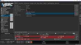
the HFI I used is the typical HFI way I following this video (
), my pilot is even worse than this, random scatters, can't observe any change when I hand turn the motor shaft.
1679883058283.png
my board is a mix of previous Easy DIY ECS and MP2, I use 6 mosfets, with 2 mΩ shunt, in order to fit with my 7S battery pack I changed the phase sense divider resistors from 100K/3.3K to 51K/3.3K, that gives more than 1.2V (logic level High) when power suppled with 20V or above. all others like amp resistor/gain keep the same as MP2. I do not use throttle, instead all control from VESC tool. except HFI, it works fine with my two motors (a small inner rotor and a larger scooter one) with hall or without (sensorless), FOC auto detect works fine as well.
 
the HFI I used is the typical HFI way I following this video (
), my pilot is even worse than this, random scatters, can't observe any change when I hand turn the motor shaft.
View attachment 331878
my board is a mix of previous Easy DIY ECS and MP2, I use 6 mosfets, with 2 mΩ shunt, in order to fit with my 7S battery pack I changed the phase sense divider resistors from 100K/3.3K to 51K/3.3K, that gives more than 1.2V (logic level High) when power suppled with 20V or above. all others like amp resistor/gain keep the same as MP2. I do not use throttle, instead all control from VESC tool. except HFI, it works fine with my two motors (a small inner rotor and a larger scooter one) with hall or without (sensorless), FOC auto detect works fine as well.
This old VESC HFI is 3+years old and is basically garbage. Please don't use it. It is not a failing of the MP2, it simply does not work properly for any hardware I have yet discovered. HFI45 is the correct one to use, Benjamin's latest HFI creation, with an applicable motor it is basically magic.

Make sure you are using the latest firmware. Anything pre VESC 5 is really quite bad, post 6 it all gets dramatically better.

If you are not actually using an MP2, then all bets are off. The specific layout is critical, it would be quite easy to make a pill/board arrangement that had a large amount of noise or was sensitive to board copper resistances. I suggest you make a thread here to examine your exact board.
 
Last edited:
This old VESC HFI is 3+years old and is basically garbage. Please don't use it. It is not a failing of the MP2, it simply does not work properly for any hardware. HFI45 is the correct one to use, make sure you are using the latest firmware. Anything pre VESC 5 is really quite bad, post 6 it all gets dramatically better.
Thanks Mxlemming, but I'm a little bit confused here, the vesc tool I downloaded is directly from vesc official website. as for the vesc firmware, I downloaded and complied directly from github -> GitHub - vedderb/bldc: The VESC motor control firmware it shall be very very new. what is the HFI45 you mentioned?
 
VESC HFI45.png
It is this. New VESC tool is black by default.

But since you are not actually building an MP2, and this is not a VESC thread...
 
ok got you, this is a misunderstanding, I use the exact the same tool with black background. the screenshot I just picked up on internet. will try HFI45 as you suggested.
 
I've been reading advancement on this DIY ESC quite often because I was looking for something capable of some good power. So first of all, thank you for sharing this badginer and thanks to all the people contributing to this !

I've recently ordered some boards ( V0.2 at the time) and assembled one of them with CRST030N10N mosfets and TF2190M-TAH gate drivers.

View attachment 328628

Now I'm in the process of making it turn something but struggle a bit with the firmware part.

My prefer choice of firmware would have been VESC because I've worked with it for a while and the communication and configuration software is quite handy. So my first try have been to swap a GD32 onto a Bluepill and run netzpfuscher Vesc implementation but so far without success. I've successfully compiled from repository then flash on the board, but no connection to vesctool with a UART to USB adaptor (Vesc report no firmware detected). I think The firmware is running since I hear the buzzing at boot. Do someone have an idea what could make vesc tool not communicate with it ? (I have already tried the rx/tx swap without better luck)

Since I had some black pills I gived a try today at Mxlemming MESC firmware but without better luck. I tried to use the live expressions on STM32CubeIDE with a STlink V3 but for whatever reason they doesn't want to update. I haven't found another easy way to figure out what's happening. Electricaly I can see the switching starting when I twist the throtle but no current is flowing and can't figure out in wich mode the firmware is at that point. Is there a way to enable Uart live data transfer ?
to compile, you have to change here the HW_M365 to HW_MP2

@netzpfuscher
I have successfully talked to Netzpfuscher firmware, however compared with VESC, the resistor detection has huge difference (around 10 times), it can not work on an inrunner but does good for an outrunner. I'm not very sure why the default gain set to 10.5 here, it shall be 21.88 isn't it?

I updated to 21.88 but no much change.
 
Is the displayed bus voltage and phase voltage (while running) in the realtime window of VESC tool correct? Is the current correct try open loop with 5A and a very low ERPM while measuring the current through one phase with a multimeter. The current then rotates and the multimeter should show a peak current of 5A.
 
Is the displayed bus voltage and phase voltage (while running) in the realtime window of VESC tool correct? Is the current correct try open loop with 5A and a very low ERPM while measuring the current through one phase with a multimeter. The current then rotates and the multimeter should show a peak current of 5A.
the firmware does not work for inrunner, though it works with outrunner, the performance is not very good compared with 405pill, the rotor spins with vibration, it draws 2 times more current than 405pill at same electrical rotation speed.

I'm interested in your idea, so I actually replaced the Xiaomi controller with GD, however it does not make any notable difference.

it is not realistic to request the same performance, however it could be very encouraging if the firmware can leverage the 405pill on some extent, say for example the detection of motor parameters, start up, low speed performance can be expected to be closer.

If you need, I can provide some data/video for you to investigate, just let me know what you want.

Anyway thanks for this great idea.
 
it is interesting to see the 4 copper layers are:
top - 3.3V
inner 1 - GND
inner 2 - GND
bottom - 3.3V
while the general rule like this:
top - signal w/o GND
inner 1 - GND
inner 2 - PWR
bottom - signal w/o GND
just wondering if there is some good reason/lesson learnt?

Hi.

So I really hoped somebody would notice and ask, and I somehow missed this until now :D
Love this kind of conversation, that's why i'm here and not drinking alone with wikipedia LOL.

First of all @mxlemming - this is the pill, not mp2. mp2 has some power planes, which I hate, because its not only one. So i wanted to see if I could do this on the Pill - I was the one who insisted on this.

The logic is the following.
1) solid gnd planes offer perfect return current path. (unlike a power plane)
2) solid gnd planes offer perfect inductance minimization. (much like power plane)

But 1 becomes a greater concern in case you have multiple power planes. if signals pass from over gnd to over 12v and then to over 3v3 power planes, return path is shit. This is not the case for the pill, but it is the case for mp2.

So this was me doing a kind of proof of concept on the pill, of a design "improvement" I wanted on the MP2 actually.

Is this multiple power plane thing actually a deal breaker? no, we don't have high Ghz signals, and MP2 works fine like this.
Am I a sucker for microoptimisations? Yes, almost fetish level I would say. And for ground planes :D


Br,
badgineer
 
Last edited:
[....] IF AND ONLY IF you are able to absolutely guarantee the decoupling of every single device on the board through localised capacitors. If you are not able to guarantee this, then foregoing a power plane will have a bigger negative impact than the benefits attained through the better signal returns.
[...]
Thanks for pointing this out :)
My idea was the following.

1) I did care for a cap on each power consumer on the MP2, and on the pill... did not take so much care but I think they are all there. But even if some are missing...
2) Check the PCB. i did not forgo completely a power plane. I mean I did, but i did not go with a thin trace of 3v3 either. I did a 3v3 pour that is as wide as I could get it in the narrowest places and well sewn together on both sides with vias. This creates sort of a capacitor between the pours and the gnd planes underneath. And the pours themselves have all some decoupling caps on them (on most or all power consumers) and close to zero inductance.

So the idea is that the super high frequency energy is taken from the field between 3v3 pour and gnd, medium freq energy is taken from decoupling caps (that are many), and low freq energy just goes through the pour and many vias.

ow, and now to be a complete weirdo about inductance and decoupling caps and go far into diminishing returns .... if you connect a power consumer with a via to a power plane and dont give it a decoupling cap.... the via is quite inductive! how dare you treat that poor power consumer like this! :D. A surface pour does not have this problem. =))

So diminishing returns? oh yeah.
Objectively better? electrically yes, I like to think.
But a pain to route in some places :D

Gee i love splitting hairs :D

Br, badgineer
 
**UPDATE: PCB MESSED UP! IF YOU USED MY MODIFIED PCB DO NOT ORDER IT!!**

Hello to everyone,

I'd like to give some feedbacks/comments/questions about this project and anything related. So far, this project out of any I've seen is outstanding. Compared to any esc repositories, this is truly open source and a beast. It is unlike what ennoid has done, claiming that the gen 1 bms is open source when in reality the actual pcb files aren't available and let alone the schematic files are corrupted and missing major battery and load terminals. Haven't seen that at all here. Speaking of a bms, does anyone recommend a good bms I could order at jlcpcb given the design files for a 100.8v 300 amp maximum setup? That would be very great. I'm basically going to use this esc for a bicycle to convert it into an ebike. I'll see how it performs and will give feedbacks and recommendations as well as updates.

Moreover, there are so far some improvements that could be made if I am not wrong. I adjusted some designs to the board due to the fact that badgineer greatfully pointed out the high cances of arcing which I was scared of. I initially tried to make the board larger but it seemed tedious and also since I am kind of a beginner at KiCad. But with some YouTube tutorials, I managed to make some modifications. For aesthetic reasons, I slightly crammed the holes of the phase wires within the phase contact areas which may probably also reduce arcing. I also added a total of 4 bus bar mounting holes, 2 each for each of the battery terminals. At first, I thought this was a stupid idea. This was because they intersected the bottom mosfets and I would have to mount the FETs vertically which would give worse cooling and probably an explosion. But fortunately, I could just use a nut for each hole mounted on the bottom of the board and then just bend the mosfet over it (OBVIOUSLY I WILL PUT INSULATION ON THE NUTS.) In case it was a bad idea, I attached the project files as a ZIP to this post AND since I love open source things so much that I would marry it (just kidding lol). I invested my own time and stayed up a couple of nights for this so hopefully my modified design to badgineer's ESC won't turn out to be a failure. To anyone on this thread, especially badgineer, it would be amazing if they could check the design files from this post and see if it is hazardous/dangerous/unfit for use at all as well as some recommendations.
 
Last edited:
Hello to everyone,

I'd like to give some feedbacks/comments/questions about this project and anything related. So far, this project out of any I've seen is outstanding. Compared to any esc repositories, this is truly open source and a beast. It is unlike what ennoid has done, claiming that the gen 1 bms is open source when in reality the actual pcb files aren't available and let alone the schematic files are corrupted and missing major battery and load terminals. Haven't seen that at all here. Speaking of a bms, does anyone recommend a good bms I could order at jlcpcb given the design files for a 100.8v 300 amp maximum setup? That would be very great. I'm basically going to use this esc for a bicycle to convert it into an ebike. I'll see how it performs and will give feedbacks and recommendations as well as updates.

Moreover, there are so far some improvements that could be made if I am not wrong. I adjusted some designs to the board due to the fact that badgineer greatfully pointed out the high cances of arcing which I was scared of. I initially tried to make the board larger but it seemed tedious and also since I am kind of a beginner at KiCad. But with some YouTube tutorials, I managed to make some modifications. For aesthetic reasons, I slightly crammed the holes of the phase wires within the phase contact areas which may probably also reduce arcing. I also added a total of 4 bus bar mounting holes, 2 each for each of the battery terminals. At first, I thought this was a stupid idea. This was because they intersected the bottom mosfets and I would have to mount the FETs vertically which would give worse cooling and probably an explosion. But fortunately, I could just use a nut for each hole mounted on the bottom of the board and then just bend the mosfet over it (OBVIOUSLY I WILL PUT INSULATION ON THE NUTS.) In case it was a bad idea, I attached the project files as a ZIP to this post AND since I love open source things so much that I would marry it (just kidding lol). I invested my own time and stayed up a couple of nights for this so hopefully my modified design to badgineer's ESC won't turn out to be a failure. To anyone on this thread, especially badgineer, it would be amazing if they could check the design files from this post and see if it is hazardous/dangerous/unfit for use at all as well as some recommendations.
Hi Dayanul,

Regarding open source - yeah, we did it all open, down into detail. Many open source projects also have commercial "sister projects" - so there is a motivation behind not giving out everything. That's not true in this case, MP2 is probably useless commercially. (tedious to assemble, pill based, etc)
Its more of a learning (or teaching) device.
We also really invested time in the readme/documentation, especially @owhite, I recommend everybody to read that.

Regarding arcing: The arcs don't start spontaneously because of some major design flaw, we just had 1 accident once. As a result, we did quite a few improvements to make starting arcs harder in v0.4. At least I like to think its better now.

If you want to start modifying something, maybe start from v0.4. there's quite some extra work that went in it, compared to.
Also, If you don't *really* know what you are doing, don't go overboard with the modifications, at this time most of the things are designed as they are for good reasons :).

Example: if you put bolts under the mosfets, you'll have to mount the mosfets further from the PCB. and at high current, the thin legs of the mosfets are a bottleneck and heat up quite a lot. Also they're inductive and make switching less clean. If you want to go over say 150A, mosfets should be mounted as close to the PCB as possible, ideally the thick part of the mosfet legs should be touching the pads on the PCB.

Ill maybe look at your files later, have very little time these days.

PS: 100.8v 300 amp maximum setup? that's almost 40 horse power... I dont think the MP2 will be able to handle this kind of power for more than ...a few seconds.
Just trying to set expectations, so you wont be disappointed later :)


Br,
 
Hi All,

Finally I'm back to testing. Now I have the VESC header files and I compiled the software, the steps I made in case anyone's attempting to match an F405 V1.1 pill with VESC on it with the V0.3 MP2:
  1. Created a VirtualBox machine with Ubuntu 22.04 (I'm on Windows host)
  2. Installed the official VESC repo, checked out release_6_00 branch
  3. Added the hw_MP2.c and HW_MP2.h (I will updload these to GH once I confirmed that everything's correct) to to bldc/hwconf/other folder
  4. Added the following line to bldc/package_firmware.py so that the make command recognizes MP2 as a device:
    package_dict["MP2"] = [['MP2', default_name], ['MP2_no_limits', no_limits_name]]
  5. Installed openocd
  6. Attached the GND, 3.3V, SWCLK and SWDIO pins of the F405 pill (not attached to MP2, no USB cable) to a chinese ST-Link v2
  7. Plugged in ST-Link to an USB port, connected it to VirtualBox's virtual USB port from it's Tools menu, now "lsusb" lists it
  8. Opened a terminal from the bldc folder
  9. Typed "make MP_flash", this command makes and uploads the binary to the pill
After that I soldered and checked everything according to the description, it's a great help.

I thought that after that it'll be easy, however I encountered the following issues:
  • The pill was ok when was not connected to the MP2, however was constantly in reset state once I connected to MP2. This was due to the NRST pin. I removed this leg, now it's ok, i didn't thy to find the root cause. Did anybody else had this issue?
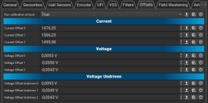
  • When I powered on the device, VESC reported FAULT_CODE_UNBALANCED_CURRENTS. I did a current calibration from VESC Tool/FOC/Offsets, the unbalanced current error was gone, but FAULT_CODE_HIGH_OFFSET_CURRENT_SENSOR_3 appeared once, but after another calibration it was gone. Could some of you compare my results to theirs, do they seem ok? The voltages on the current sensing pins are around 2.1V, is it ok?
    calib.png
  • FAULT_CODE_BRK is contantly triggered due to a low voltage on PB12, did anybody else have this issue?
  • My opamp (COS724) gets slightly warm during operation, is it normal?
I will continue the testing soon
 
Hi All,

Finally I'm back to testing. Now I have the VESC header files and I compiled the software, the steps I made in case anyone's attempting to match an F405 V1.1 pill with VESC on it with the V0.3 MP2:
  1. Created a VirtualBox machine with Ubuntu 22.04 (I'm on Windows host)
  2. Installed the official VESC repo, checked out release_6_00 branch
  3. Added the hw_MP2.c and HW_MP2.h (I will updload these to GH once I confirmed that everything's correct) to to bldc/hwconf/other folder
  4. Added the following line to bldc/package_firmware.py so that the make command recognizes MP2 as a device:
    package_dict["MP2"] = [['MP2', default_name], ['MP2_no_limits', no_limits_name]]
  5. Installed openocd
  6. Attached the GND, 3.3V, SWCLK and SWDIO pins of the F405 pill (not attached to MP2, no USB cable) to a chinese ST-Link v2
  7. Plugged in ST-Link to an USB port, connected it to VirtualBox's virtual USB port from it's Tools menu, now "lsusb" lists it
  8. Opened a terminal from the bldc folder
  9. Typed "make MP_flash", this command makes and uploads the binary to the pill
After that I soldered and checked everything according to the description, it's a great help.

I thought that after that it'll be easy, however I encountered the following issues:
  • The pill was ok when was not connected to the MP2, however was constantly in reset state once I connected to MP2. This was due to the NRST pin. I removed this leg, now it's ok, i didn't thy to find the root cause. Did anybody else had this issue?
  • When I powered on the device, VESC reported FAULT_CODE_UNBALANCED_CURRENTS. I did a current calibration from VESC Tool/FOC/Offsets, the unbalanced current error was gone, but FAULT_CODE_HIGH_OFFSET_CURRENT_SENSOR_3 appeared once, but after another calibration it was gone. Could some of you compare my results to theirs, do they seem ok? The voltages on the current sensing pins are around 2.1V, is it ok?
    View attachment 334069
  • FAULT_CODE_BRK is contantly triggered due to a low voltage on PB12, did anybody else have this issue?
  • My opamp (COS724) gets slightly warm during operation, is it normal?
I will continue the testing soon
Several people have had the BRK issue and in all cases it's been because of soldering. Some have overridden it and learned the hard way the BRK really does mean there's a problem

Your voltages should be 1.6V on the opamp outputs and offsets should be closer to 2048. I think we've seen functional with add much as 200 counts different but 1500 indicates a problem. BRK pb12 should be 3v3.

The opamp shouldn't get warm. How do you know it's getting warm? Isn't it hidden under the pill?

Have you checked and confirmed the 12V 5V and 3v3 rails are correct?

Please add pics to your post, more likely to help us diagnose things.

Fortunately/unfortunately every problem so far (excluding owhite's suicide FETs) has either been due to bad soldering or the knock on effects of fitting components backwards/shorting components out.
 
......................
  • FAULT_CODE_BRK is contantly triggered due to a low voltage on PB12, did anybody else have this issue?
......................
Hi.

This sounds similar to a problem somebody had before.
The BRK (PB12 low) is triggered as overcurrent or overvoltage protection. Your current imbalance error also points to this.

*** do not ignore this - it might be a serious issue ***

In the case i mentioned it was a bad gate resistor that caused one fet group to turn off too late, (after the fet group across was already on), and thus shorted the battery through the fets on each pwm. User ignored it, and it ended immediately with vaporized parts...

Check your opamp (which controls the pb12) and your gate signals (which control the fets)

Br,
 
Thanks for your quick replies!
I forgot to mention that my problems persist even if no motor is attached and if only external 3.3V is applied without Vbat and the pill. So based on this and on your valuable inputs it's pretty obvious that something around my opamp is not ok. So I tried another board, luckily I have 5, and on the new one I can see 1.6V on the current sensing outputs and 3.3V on the BRK as expected, so I'm happy.
I didn't have time to find the root cause of the wrong signals on my first board but I think that I'll move forward with the new one and check back on this issue later on.

Yes opamp is hidden under the pill, but I'm cautious with newly built boards especially if something seems off, so I disassemble the parts right after short usage and touch every component to check for heat, this way I already saved several components from blowing so it became a routine :)

Other question: what is the part number of the NTC that you used? I soldered a random 10k one and it reports -0.8C° at room temperature
 
Definitely some improvements! Only thing there's no screw hole for bus bars. I discussed this with badgineer looks like it's due to there being a risk of thermal expansion between the copper bus bar bending the pcb. Either way I'll work on an idea in mind. Also DO NOT use the files I posted last week they have major errors. Another thing, there seems to be 3 holes names gsA gsB gsC and doesn't show those pins on the schematic. Plus there are 3 unnamed holes. I'm assuming they are test points.
 
Definitely some improvements! Only thing there's no screw hole for bus bars. I discussed this with badgineer looks like it's due to there being a risk of thermal expansion between the copper bus bar bending the pcb. Either way I'll work on an idea in mind.

I've heard this mentioned a bunch, but the copper layers in the pcb would likely separate / delaminate as well if it was an issue. Does someone have a documented incidence of this happening? I know it can bend if they're soldered at different temps as it cools - avoid doing that.

Also DO NOT use the files I posted last week they have major errors.
Consider editing the post and removing the file. That way no one accidentally grabs the wrong file trying to make one of these.
 
Several people have had the BRK issue and in all cases it's been because of soldering. Some have overridden it and learned the hard way the BRK really does mean there's a problem
And because of noise on the lines. @mxlemming , recall that I was throwing errors that went away after I put a cap across the throttle pin on the F405 pill and ground.

@Dayanul Alam please note there is a readme with soldering help for the MP2 here.
 
Last edited:
I've heard this mentioned a bunch, but the copper layers in the pcb would likely separate / delaminate as well if it was an issue. Does someone have a documented incidence of this happening? I know it can bend if they're soldered at different temps as it cools - avoid doing that.


Consider editing the post and removing the file. That way no one accidentally grabs the wrong file trying to make one of these.
Is it only because of the thermal expansion? What if I used segmented bus bars? Plus if I screwed the pcb like a motherboard onto some solid firm material, the pcb won't warp right?
 
Back
Top