MOSFET Switch for remote controlling an ebike

azad

10 W
Joined
Sep 20, 2019
Messages
96
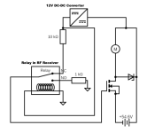
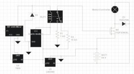
I've connected an N-Channel MOSFET (https://pdf1.alldatasheet.com/datasheet-pdf/view/52370/FAIRCHILD/FQP30N06L.html) with the motor controller and tried to control it using a RF remote receiver. RF receiver has an MCU that triggers the relay. The motor runs at 54V while the RF receiver runs at 12V so, there is a DC-DC converter that supplies the source voltage for the receiver. The gate of the MOSFET is driven by +12V from the converter and is shut by connecting it to the ground. The circuit works fine for a while (or at-least when not connected to the motor) but when in operation the MOSFET becomes damaged. I have also placed a flyback diode however, MOSFET is still getting damaged. The gate becomes ineffective permanently and it doesn't stop the flow of current even when connected to the ground. A gate-source shortage is then observed.

Update: The MOSFET gets damaged when not running the motor even once. Maybe even without connecting the motor at all. There is an alarm module in the circuit as well that I am powering from the point where the relay coil is connected.
circuit.png
 
Inductive load doubles the drain voltage when MOSFET opens. You need a 120V transistor.

EDIT: After you changed your schematic to show a controller instead of a DC motor, there is no inductive load, so my answer doesn't apply.
 
azad said:
I've connected an N-Channel MOSFET (https://pdf1.alldatasheet.com/datasheet-pdf/view/52370/FAIRCHILD/FQP30N06L.html) with the motor controller and tried to control it using a RF remote receiver.
circuit.png

1. The relay wiring isn't drawn correctly (it's coil would be powered from the rf circuit, not from the converter output).
2. Does the battery pack have common ground with the other ground symbols? It should.
3. I assume the converter is drawn as the HV positive in to LV positive out. Is the input and output also grounded with the common ground? It should.
4. Driving a mosfet gate with 10k is going to be faaar too slow. It might be running in the linear region for too long and out of the safe operating area. Particularly if your controller has large capacitors to precharge (large initial inrush currents). Try 100 ohms.
5. As mentioned, the mosfet voltage is too low, and leaves no headroom for transients. I would go minimum 80v, better 100v. 120v would be fine also.
6. You don't mention current handling requirements, or whether the mosfet is appropriately rated (and or heatsinked) for the load. Assuming everything is wired correctly, are you just overloading the mosfet?
 
docw009 said:
Inductive load doubles the drain voltage when MOSFET opens. You need a 120V transistor.

The MOSFET even gets damaged when not running the motor at all. Not even connecting with the controller.
 
serious_sam said:
azad said:
I've connected an N-Channel MOSFET (https://pdf1.alldatasheet.com/datasheet-pdf/view/52370/FAIRCHILD/FQP30N06L.html) with the motor controller and tried to control it using a RF remote receiver.
circuit.png

1. The relay wiring isn't drawn correctly (it's coil would be powered from the rf circuit, not from the converter output).
2. Does the battery pack have common ground with the other ground symbols? It should.
3. I assume the converter is drawn as the HV positive in to LV positive out. Is the input and output also grounded with the common ground? It should.
4. Driving a mosfet gate with 10k is going to be faaar too slow. It might be running in the linear region for too long and out of the safe operating area. Particularly if your controller has large capacitors to precharge (large initial inrush currents). Try 100 ohms.
5. As mentioned, the mosfet voltage is too low, and leaves no headroom for transients. I would go minimum 80v, better 100v. 120v would be fine also.
6. You don't mention current handling requirements, or whether the mosfet is appropriately rated (and or heatsinked) for the load. Assuming everything is wired correctly, are you just overloading the mosfet?

1. Updated the schematics
2. Yes! battery is connected to the voltage regulator and which in turn gives power to all other electronics.
3. Yes! updated the schematics, it now handles that.
4. I was trying to be cautious, blew 5 MOSFETS so far, initially I did use lower resistance or not at all.
5. But MOSFET is even getting damaged without running the motor!
6. Yes! it is rated at 30A and max current draw is 18-20A for the whole system.
 
azad said:
5. But MOSFET is even getting damaged without running the motor!
6. Yes! it is rated at 30A and max current draw is 18-20A for the whole system.
Inrush current for an uncharged capacitor is extremely high if not limited by a precharge resistor. Many people have blown up many mosfets because of this. If your mosfet switches power to a motor controller that has large capacitors (which most have), then there will be an extremely high instantaneous current through the mosfet.

You could try putting a large (5-10 Watt) 100ohm resistor in series with the controller. Don't operate the motor like that, but just charge and discharge the controller capacitors a bunch of times (switch it on and off, and wait a minute in between to allow the caps to internally discharge) and see how your mosfet lasts.

Alternatively, try a higher capacity mosfet like 100A 100V.
 
serious_sam said:
azad said:
5. But MOSFET is even getting damaged without running the motor!
6. Yes! it is rated at 30A and max current draw is 18-20A for the whole system.
Inrush current for an uncharged capacitor is extremely high if not limited by a precharge resistor. Many people have blown up many mosfets because of this. If your mosfet switches power to a motor controller that has large capacitors (which most have), then there will be an extremely high instantaneous current through the mosfet.

You could try putting a large (5-10 Watt) 100ohm resistor in series with the controller. Don't operate the motor like that, but just charge and discharge the controller capacitors a bunch of times (switch it on and off, and wait a minute in between to allow the caps to internally discharge) and see how your mosfet lasts.

Alternatively, try a higher capacity mosfet like 100A 100V.

But how can current be more than the current battery can provide?
are you sure that the problem lies at the drain and not at the gate? Remember it is the gate that is getting damaged and not the source-drain route.
I have exhausted all the MOSFETS I had, ordered IRF540PBF (100V 28A), will see how these go.
 
serious_sam said:
Inrush current for an uncharged capacitor is extremely high if not limited by a precharge resistor. Many people have blown up many mosfets because of this.

:thumb:

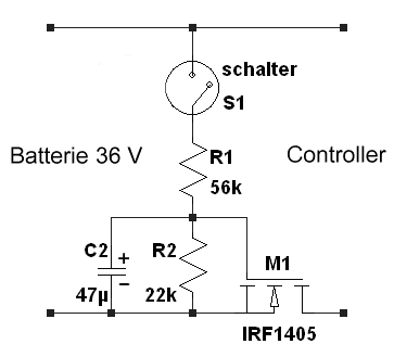
You have to use an "anti-spark" circuit. Charge the gate slowly, so the resistance from drain to source decreases slowly. This will avoid high current peaks at switching.

2428.png


regards
stancecoke
 
azad said:
But how can current be more than the current battery can provide?
are you sure that the problem lies at the drain and not at the gate?
I'm not "sure" what the problem is. I can only throw ideas at you across the internet...

Even if your battery is only "rated" for 20A, it will have a much higher short circuit current.

I = V / R (where R is the internal resistance of the pack)

For example, I use 150A max out of my 84V pack, but the internal resistance is 0.1ohms, so in theory it can deliver up to 84V / 0.1ohms = 840A for a very short duration... nearly 6x the rated maximum...

When your capacitors are discharged, your circuit is almost a short circuit. All you have is the battery IR (~0.1ohms), plus the capcitor ESR (~0.1ohms), plus some wire (~0.1ohms) and your mosfet Rds (~0.1ohms), so the entire circuit only has ~0.4ohms. So when you turn on the mosfet, you're putting 54V / 0.4ohms = 135A. The pulse rating for your mosfet is 128A, so that is really pushing it to the limit.

Anyway, that is just approximate numbers. I'm not saying that is the cause of your problem. I'm just saying, you need to take these things into consideration. Whether it's the cause of your problem or not, you're putting too much stress on the mosfet (both voltage and current). Like I said, if you want reliability, you want 100V 100A mosfet, and put it on a heatsink.
 
stancecoke said:
You have to use an "anti-spark" circuit. Charge the gate slowly, so the resistance from drain to source decreases slowly. This will avoid high current peaks at switching.
That's a good idea.
 
stancecoke said:
serious_sam said:
Inrush current for an uncharged capacitor is extremely high if not limited by a precharge resistor. Many people have blown up many mosfets because of this.

:thumb:

You have to use an "anti-spark" circuit. Charge the gate slowly, so the resistance from drain to source decreases slowly. This will avoid high current peaks at switching.

2428.png


regards
stancecoke

Tried this with IRF540 and the switch works so far but motor doesn't turn. Just Makes noises and gives jerks as if there is either very low current or not smooth enough.

Had to remove the capacitor and reduce the gate resistance to 100ohm for the current to flow.
 
Back
Top