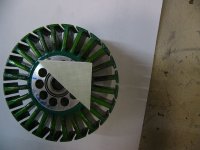
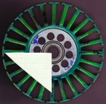
Motor comparisons [CA120 et al.]

toolman2 said:
so, i had splinteroz and zappy over and ran up some motors on a test rig that measures exact NM and rpm of the motor whilst its being driven via chain an sprockets by a 3hp lathe, the motor being tested needs no electrical connections at all and i believe we are now measuring the very lowest no load losses you could ever hope to achieve with a controller running it (prolly cant ever quite get there, but it gives something to aim for) we even tested a motor with and without windings to find the eddy current losses from the copper alone.

it got a bit wild at 10krpm for the big outrunners so it was handy to have a few of us (all using the safety squint) to quickly get the data before stuff went wrong, and eventually the limit was that the lathe only had 3hp..

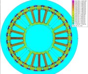
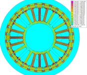
one thing that caught our interest is that (with the old ca120) the magnets got clearly hotter than anything else, and it was of their own accord not just heat passing on from what was evidently a cooler stator. :?: heres some results, and yes the new ca120 is crap cos it has .5mm lams and its just clearly lower quality allover. comments welcome.


Damn, shame I missed the testing session. Some very interesting results. Disappointing my new CA120 is such pile of crap, though should be OK at the lower end on the performance spectrum, around 3000 rpm max should be fine.
 
toolman2 said:
sorry ive not had a chance to get to this proply, but the new ca120 (from hc that is) motor is pretty different, although the results may be similar in the end. more to come.

also, can folks advise if i use a function generator (20khz sine wave say?) that says it has 50ohlm output onto my phases and look for the resulting (very small but repeatable) ripple on the windings etc ? -dunno, or maby i should do this and at least compare the ripple to that of an 80-100 130kv or 180kv that i have, that has a known inductance from others who have measured it with a proper meter?
could do with a little educating on this if possible? but ill then post up the results.
Very good you have the function generator. Set it to 20kHz square (non sine) signal and capture a waveform. We should be able to calculate inductance from that.
 
Lebowski said:
Toolman, do you have a plot for identical motors, with (wound in delta) and without copper windings ? It'd be very interesting to see the results

why yes lebowsky but its in wye cos delta is silly, heres a shot of the data that was used to make the graph, but also with the losses from a copperless stator in green, there are also torque numbers in NM, the 753w in red is actually 628w.
these numbers are giving us way more accuracy that the non detailed graph, 1125w at 10krpm with copper drops to 921w so 204w of losses are copper eddy currents? -and these are the super thin (176 of them per phase) standard windings. how will the 23g (40% higher copper fill) rewind go i wonder?

P1310031.JPG

and yes sorry brian, i should have let you know so you could drop round to smell your motor at 1411w loss. :)

i heard there could be some femm work on this miles! so heres a pic of the stator with 1mm graph paper in the shot, and anyone who wants the 8mb super quality flat scan let me know an email to shoot it to.


and thanks curcuit, i got around 13uh for this original ca120 motor without magnets but in wye (quite sensitive to rotor position with the bell on) i got closer to 12uh for the new ca120 and around 10.8uh for the collusus
if anyone wants a rotormax 150cc (hacker a200) then ill order one from hc, test it, show the results, and send it to you after a quick "run in". :wink:

and while we have the smart people here, any thoughs on thinner lams reducing the mag heating?, or would it make no difference?
 

Attachments

  • p130028.6.jpg
    p130028.6.jpg
    160.7 KB · Views: 3,265
toolman2 said:
thoughs on thinner lams reducing the mag heating?
Not directly AFAIK. How thick are the magnets? Do you have any way to measure their strength?

It would be interesting to replace them with a series of block magnets (multi-magnet poles) and see how much that reduces their internal losses.
 
Miles said:
Do you have any way to measure their strength?

Anyone have experience of these cheapo chinese gaussmeters?
http://www.ebay.co.uk/itm/Tesla-Gaussmeter-Digital-Magnetic-Flux-meter-2000mT-DC-/190540892174?pt=UK_BOI_Electrical_Test_Measurement_Equipment_ET&hash=item2c5d1f480e
 
That skinny long stator tooth looks like instant saturation. I wonder what it looks like in femm?
 
Farfle said:
That skinny long stator tooth looks like instant saturation. I wonder what it looks like in femm?
I'll finish off the model and then we can play around with it.

I need the airgap distance, magnet size and can thickness.
 
Excellent work Miles!!
The magnets on the old model CA 120 are 4mm thick 10mm wide 30mm long.
Back iron only 1.6mm!
Air gap .5mm with feeler gauges
I had to make a micro depth gauge to measure magnet thickness in the bell but these measurements should be very close.
Zappy
 
Hi zappy,

Ok. Thanks.

1.6mm... :shock:

That all adds up to 118.2mm OD....

What shape are the magnets? Are the sides radial or parallel? Or, they're just rectangular blocks?
 

Attachments

  • CA-120-close-up.jpg
    CA-120-close-up.jpg
    35.4 KB · Views: 3,271
file.php


Ref: http://www.endless-sphere.com/forums/viewtopic.php?p=311848#p311848
 
yes, all roughly correct.

excact sizes are 105.99mm stator 106.86mm magnets id, giving .44mm air gap and the mags are flat and rectangular.
the can od is 118.36mm (and assuming mags come in metric 4mm) this gives 1.75mm of back iron.
the can is 3mm thick at the skirt bearing end only, stepped down like the above photo to 'contain' the mags.
and i get 4.17mm main tooth width and 11.4mm to meet the mags -all still with green stuff so yep 4mm tooth.

also as shown theres no bevel inside where this 4mm turns to 11.4, so the majority of this 11.4mm face only measures 1.8mm -unlike the bevelled shape i see on your tooth designs miles..

this motor is known for having a fair bit of stray mag field outside the can, now we know why, i was supprised to find there were no extra rpm losses when i put it in my bikes round alloy gearbox casing with only 1mm clearance to the can.. :?


and yes thanks neps, those hk rotormax motors look pretty good to me too, .2mm lams, shorter teeth etc =way more revs, bit less torque. so the same goes for that $224 one, anyone want one? -for now ill rpm test anything folks want to send me, (might try probe magnet temp properly next) and send it back to you. (2000w mac, neps?)
 
I guess one could try with 1.2mm x 4mm magnets with the polarity across the width? Bond them together in groups of 8 for each pole, at the correct radius and then bond the groups to the can.... Black epoxy coated for insulation.
 

Attachments

  • multi-magnet-poles.jpg
    multi-magnet-poles.jpg
    27.7 KB · Views: 3,247
Miles said:
With N30 magnets.

Maximum flux density in the back-iron 2.35T

awesome miles! thanks.
-2.35T, has to win a prize, no? :D -what does this mean for high rpm losses? -could it be that the back iron itself is where this heat is coming from?
and whats a guess for peak torque before saturation?
 
I re-ran the analysis with the corrected geometry. The change to rectangular block magnets made a difference because of the additional "gap" between the magnet face and the can.
 

Attachments

  • CA-120-7.jpg
    CA-120-7.jpg
    337 KB · Views: 3,210
Increasing the can thickness to 3mm has eliminated stray flux and reduced the peak flux density in the can to 1.6T. However, it hasn't made a lot of difference to the flux density level in the airgap...

The peak flux density in the stator teeth heads is 2.252T, well into saturation. On the active teeth heads, it's around 2T.
 
toolman2 said:
-2.35T, has to win a prize, no? :D -what does this mean for high rpm losses? -could it be that the back iron itself is where this heat is coming from?
AFAIK, the only consequence of saturating the back-iron is stray flux and hence a lower flux density in the airgap.
 
Back
Top