Motor spinning problem at idle ? cogging, stalls...

JuhaHoo

1 µW
Joined
Feb 9, 2023
Messages
1
Hi all,

Two years ago I built my first electric scooter with 48V 360W hub motor with 350W KT sine wave controller, works fine, no issues. Then I got a new frame and built the second one with 48V 500W motor with KT 500W sine wave controller. Now I got problems.

I have motor connected to a controller with their original wires and connectors and a thumb trigger. I have Aim-TTI CPX400SP power supply with 48V output and current limit is set to MAX. This power supply should give around 400Ws.

I push slowly the thumb trigger, motor spin up and I slowly push further, motor accelerates but at some point it starts cogging, like going out of sync and power supply current limit triggers. Motor spins in the air with no load. Motor runs smooth and quiet until cogging starts. Motor is sensored.

I switched the thumb trigger from my other scooter, tried again, same happens.
I then switched the controller from my other scooter, same happens.

I did not dare to connect it to a battery because these issues.

Is there anything that KT controllers require like matching the motor to the controller via programming or tuning ? Didn't do anything with my first scooter, worked fine from the start.

Hope you can give me a hint what should I try next, I have oscilloscope and other equipment in hand.

This is the motor:
Controller:
Thumb trigger:

Thanks.
 
Last edited:
Sounds like a hall/phase mismatch. Do not assume that the colors on the wires match. You may need to try different combinations of wiring to get it right. Some controllers have a "self-learn" function that does this automatically.
 
Two years ago I built my first electric scooter with 48V 360W hub motor with 350W KT sine wave controller, works fine, no issues. Then I got a new frame and built the second one with 48V 500W motor with KT 500W sine wave controller. Now I got problems.

I have motor connected to a controller with their original wires and connectors and a thumb trigger. I have Aim-TTI CPX400SP power supply with 48V output and current limit is set to MAX. This power supply should give around 400Ws.

I push slowly the thumb trigger, motor spin up and I slowly push further, motor accelerates but at some point it starts cogging, like going out of sync and power supply current limit triggers. Motor spins in the air with no load. Motor runs smooth and quiet until cogging starts. Motor is sensored.

I switched the thumb trigger from my other scooter, tried again, same happens.
I then switched the controller from my other scooter, same happens.
That last step indicates there is a problem with the motor itself, or it's wiring, or it's hall sensors, or the wiring order combination of phases and hall sensors.

If the controller has a self-learn feature, try that first. If it does not, you'll need to manually try changing the order of the phase wires until it spins smoothly at low current at the expected speed. If the direction is reversed, then swap the hall wires until it spins smoothly at low current at the expected speed.

If this doesn't work, then check the hall sensors for valid signals during manual motor rotation using a multimeter, or if you have an oscilloscope you can check them while the motor is running.
 
After 2 week vacation, I'm on this again. This is what I found:

Sensor signals look good, there is 120 degree difference between each sensor phases. Signal shape looks all fine. I tested this by turning the motor by hand and checking all the sensor signals related to each other.

Motor starts spinning when I slowly speed up the motor with thumb trigger. It draws around 300mA of current at 36V. When it reach a certain speed point it stalls and current limit goes off. When I try to rapidly accelerate the motor, it also stalls immediately. Until that point motor turns smooth. However sometimes it keeps rough sound at very low speed too but keeps spinning.

I tried switching hall sensor signal wires, but with any other combination it refuses to spin completely, so this is no go.

I'm kind of situation to open the motor and see is there anything suspicious inside because I tired another controller and it does the same.
This is also a different thumb trigger so this is also ruled out.
 
It could be a short in the phase wires, but I'd expect that to immediately overload the controller. If there is a short between turns on a winding, it may be very difficult to locate, or even test for. With a shorted turn, the motor would have increased resistance to spinning by hand, but not as much as a short between phase wires.
 
Can it be, that some controllers and motors have a mismatch? There is no learning mode available for this controller as far as I know of it. These two controllers I have are from the same supplier but with different power ratings. The electronics could be close to similar between the two which could explain why they both failed to spin this particular motor.
Is there any way to check this than buying another type of controller? Can the phase voltage vs sensor voltage tell something? I could hook up the oscilloscope to the phase voltage adjacent to sensor voltage and see what happens on that critical point now that I have the setup ready.
 
Can it be, that some controllers and motors have a mismatch? There is no learning mode available for this controller as far as I know of it.

The safest or most conservative assumption is that they are all mismatched, then be pleasantly surprised if they match.

This article and flow chart may be helpful in determining the correct/matching hall sensor and phase wire combination that works
 
The safest or most conservative assumption is that they are all mismatched, then be pleasantly surprised if they match.

This article and flow chart may be helpful in determining the correct/matching hall sensor and phase wire combination that works

I tried this method but any other wiring combo and the motor refused to spin, so the sensor phase relation must be correct.

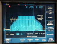
I hooked my oscilloscope to the Yellow sensor wire and to the Yellow phase wire and this is how it looks like.
Sensor wire has a lot of interference and this is because the sensor wires and motor wires are packed into one cable and they pick up noise from the motor I guess. Does this look like a normal to you ?

1679604822433.png


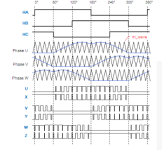
I took a screenshot from the sine wave controller signals from on web page..

1679605009603.png
 
Back
Top