
Metallover
10 kW
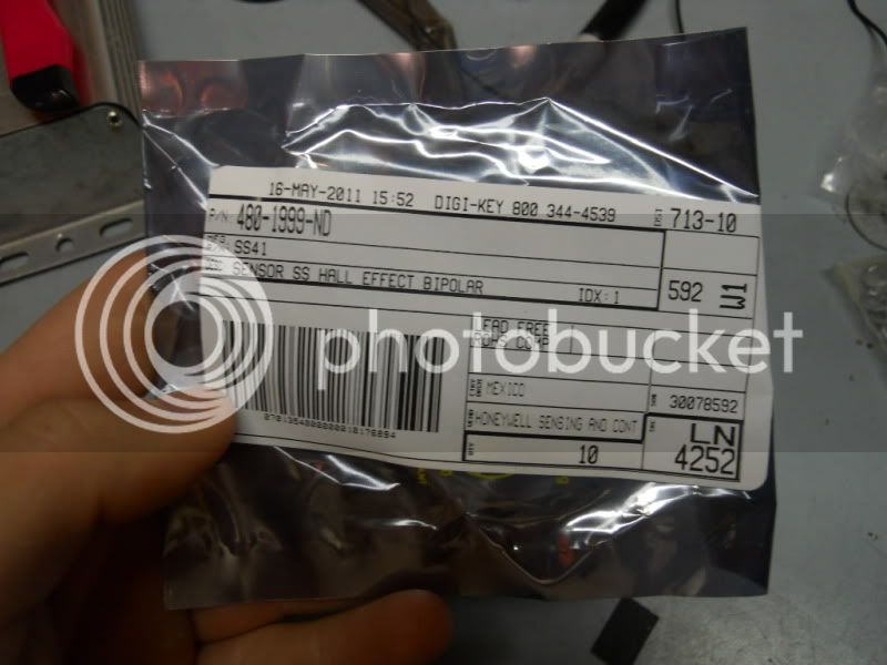
I just received ten 480-1999-ND Honeywell "Sensor SS Hall Effect Bipolar" SS41 hall sensors from digikey. link
Datasheets SS40 Series
Product Photos TO-92 Pkg (Short Body)
Product Training Modules Magnetic Sensors
Standard Package 1,000
Category Sensors, Transducers
Family Magnetic - Hall Effect, Digital Switch, Linear, Compass (ICs)
Series SS41
Sensing Range 150G Trip, -140G Release
Type Bipolar Latch
Voltage - Supply 4.5 V ~ 24 V
Current - Supply 15mA
Current - Output (Max) 20mA
Output Type Digital, Open Collector
Features -
Operating Temperature -40°C ~ 85°C
Package / Case TO-92-3 (Short Body)
Packaging Bulk
Supplier Device Package Radial Lead
Catalog Page 2735 (US2011 Interactive)
2735 (US2011 PDF)
Other Names 480-1999
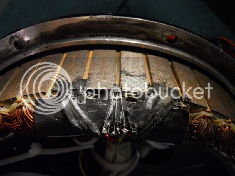
I installed one to replace my blown sensor, and put everything back together. When I tested it out, I got some ugly sounds and sights from the motor. I tested the halls with everything plugged in,, Insert the black lead into the black wire and the red lead into each of the hall's third wire's port. Then I slowly turned the motor and looked at the voltage.
The original two sensors function perfectly fine. Voltage switches from 0V to 5V as I turn the motor. The new sensor does not; It stays at 5.1V when I turn the motor.
I thought maybe I had damaged the sensor in some way when I installed it, so I tore everything up again and replaced my new sensor with another new sensor.
The same problem persists. 5.1V all the time.
Did I get the wrong sensors? Can someone link me to the right sensors if I did? :|
I noticed my sensors say "032" Instead of "028" as seen in this thread.. That's the problem??

(joints suck but they are tested & good)
Datasheets SS40 Series
Product Photos TO-92 Pkg (Short Body)
Product Training Modules Magnetic Sensors
Standard Package 1,000
Category Sensors, Transducers
Family Magnetic - Hall Effect, Digital Switch, Linear, Compass (ICs)
Series SS41
Sensing Range 150G Trip, -140G Release
Type Bipolar Latch
Voltage - Supply 4.5 V ~ 24 V
Current - Supply 15mA
Current - Output (Max) 20mA
Output Type Digital, Open Collector
Features -
Operating Temperature -40°C ~ 85°C
Package / Case TO-92-3 (Short Body)
Packaging Bulk
Supplier Device Package Radial Lead
Catalog Page 2735 (US2011 Interactive)
2735 (US2011 PDF)
Other Names 480-1999
I installed one to replace my blown sensor, and put everything back together. When I tested it out, I got some ugly sounds and sights from the motor. I tested the halls with everything plugged in,, Insert the black lead into the black wire and the red lead into each of the hall's third wire's port. Then I slowly turned the motor and looked at the voltage.
The original two sensors function perfectly fine. Voltage switches from 0V to 5V as I turn the motor. The new sensor does not; It stays at 5.1V when I turn the motor.
I thought maybe I had damaged the sensor in some way when I installed it, so I tore everything up again and replaced my new sensor with another new sensor.
The same problem persists. 5.1V all the time.
Did I get the wrong sensors? Can someone link me to the right sensors if I did? :|
I noticed my sensors say "032" Instead of "028" as seen in this thread.. That's the problem??
(joints suck but they are tested & good)