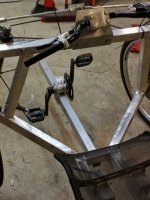
My Velo Pedal Car Prototype

After much thinking and finding 10$ headsets with a 1" bore on amazon https://www.amazon.com/Sunlite-Thre...d=1467841796&sr=8-1&keywords=headset+threaded I decided to move those bronze bushings to the upper end of the steering kingpin rods and put the headset bearings on the lower end. Basically, where I should have been in the first place but the difficult to find information and poorly labeled item information on bicycle components had me running for the more standardized industrial taper bearings. Bicycle parts need clearly labeled standardization numbers on every store page. So many competing designs. ASME needs to get involved and straighten them out.

Going to cut the threads off the spindle and tap the end of it for a lower profile way to secure the wheels while saving weight and looking more elegant. While I'm at it I'm going to cut the kingpin 1" round bar steel rod off above where the bicycle headset bearings will mount and weld on a section of thin wall tubing to replace the solid round bar. Might even just replace the entire solid round bar with some stainless 1" OD tube. At the moment the spindles are only tacked into a drilled hole in the round bar. With the cast iron flange bearings and pillow blocks replaced with headset and bushings and the round bar replaced with tubing, I might save about 15 pounds while reducing the ride height significantly as well as the CofG. Only a few hours of work.

Found this for those who need it.
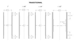
headtubespecs.jpg

It was in here: https://www.canecreek.com/resources/products/headsets/technical-specifications/headset-tech-specs-rev-e.pdf
 
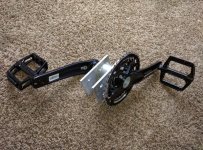
BB30 crankset on the way. willing to pay extra for a press fit bottom bracket to prevent having to machine right and left hand threads. That would save a lot of money, though. Will have parts machined before they arrive
 
BMS, 2 more battiers for 24s 1.15KWH capacity and 350W onboard charger on the way. Range will be between 25 and 50 miles with 3.5 hour recharge time. have to take a week off from building it for vacation.

When I get back the crankset goes in with the batteries and a little more testing and perhaps a ride to work and back then it's on to the body. Not sure what to use for the material yet. Need something rigid enough that bumps don't make it rattle or warble like sheet metal. Please make a suggestion. Not totally against wood. Can do a thin walled tubular aluminum skeleton

https://www.youtube.com/watch?v=DcxOyHCRic8
 
Coroplast (old election signs) have been the best compromise material I've used so far, that isnt' all boomy or noisy, but it's hard to keep painted. :/ I've not built a full body but I"ve used it for fenders, "fairings", side panels, etc., including a whole-frame covering on CrazyBike2 for a while. I just used zipties to hold it on, and clear packing tape (replaced as needed) for any water-resistance I needed at seams.

SB Cruiser just has (had, as I need to make new oens for the changed-design fender frames) fenders, but it reduced the noise from the road and the freewheel when they were on there, and frame covers over the wiring in front; if I had large enough sheets of it I'd make a sun-shield-roof top out of it, but for that I'll have to use cloth stretched over an old folding cot frame.
 
Yeah! Big fan of it. Subscribed to your YouTube channel already. I kind of like the wood idea so I can put a hipster vintage stained and polyurethane finish on it. Easy to work with.
 
amberwolf, I'm not against that type of material so long as it can be bent slightly without wrinkling and is easy to get a hold of. I see it for cheap at home depot as "twinwall plastic sheet." It just looks really cheap as the corrugations are probably always visible.
 
It depends on how you design the body and panels.

The corrugations might show a lot or might not dpeending on how close you are, etc. If it's really important that you have a perfect smooth finish, then coroplast is probably not your best option--casting fiberglass, polishing it, and then painting or clear-coating it would be much more perfectly smooth. (same with wood).


If you look at my SB Cruiser pics you can see what it's like in use as flat panels. Trying to curve it will depend on how you do it how good or bad it looks--I'm terrible at that sort of thing so I don't usually try it. ;)


Li-ghtcycle has a thread about a bike with a big cargo pod on the back made from coroplast, if you wanna see the stuff in another configuration.

I think ddk's solar trike uses it for part of the box-body.

As for cheap sources....I just recycle election signage, cuz when voting is over it's just uncollected trash sticking out of the ground at that point. ;)

Some of them are quite large, some small. Most of what I have right now is a whole bundled stack of unused identical ones someone tossed out about 3 years ago. A few others are old retail signage from sales and whatnot. Mostly, common spraypaint sticks ok to it, but it's better if you rough up the surfaces first. (and depends on what inks they used if you are re-purposing old signs).


The main thing I like about it is that unlike big sheets of thin wood it isn't all that boomy from vibrations, as it doesnt' all flex in the same way at the same time, and I think the corrugations tend to damp out what vibrations there are.

But I haven't tried to build an enclosure that *I'm* riding in, yet. ;)
 
nerdalert - correct me if I'm wrong, but from the photos and vid of your ride, it doesn't look like you've followed 'normal' principles of steering design, including taking scrub radius in to account? It looks like your stub axles are connected directly to the upright at 90 degrees to the upright (which would mean a hugely positive scrub radius). It could just be that I can't see it properly.

Just mentioning it, because in relation to your brake-steer problem one of the recommendations is to have a slightly negative scrub radius. The other common recommendation is to have both front brakes activated by the same cable, either by using a cable splitter or by physically in-lining the calipers to the same cable. This reduces the occurrence of brakes applying uneven force to each of the wheels.

Here are some good resources I've found:
Recumbent trike design primer (Hellbent cycles)
Tribolt trike steering page
 
The brake-steer is light with maximum braking at 30mph. What you're seeing is an illusion. The kingpin inclination angle draws a line in front of the wheel but not outside or inside of the contact path giving a trailing tire setup. It handles great and self centers. With all steering setups, especially where there is wheel offset there are compromises. 15 degrees kpi 5 degrees camber 12 degrees caster if my memory serves me right.

Have dual cable lever. The calipers just suck ass. Bb7's en route. Going on vacation for a week starting tomorrow when I get back all my parts will be here
 
NOPE! Something similar to yours would be the natural shape I would choose for the front end but the rear end will be a balance of the need for storage space, ease of tube rolling and fabrication (may not be a one off), and aesthetics. I've not put that much thought into at this moment as I just returned home from vacation to finish the mechanical components. Still waiting on the BMS and the charger. I want to be able to plug in an extension cord and walk away.

I've been toying with the idea of selling them locally as I live near one of the USA bicycle capitals (Portland) so I have been designing around speed and ease of assembly and at a much lower price point than existing designs. The main motivation being a desire to provide an affordable alternative to internal combustion transportation and not just a social or fashion statement. But that's an afterthought as I haven't yet proven it is something I enjoy to ride to work every day. At this point it isn't a business endeavor but an intellectual project as I could easily drive my 50+MPG low maintenance motorcycle to work.

By the way, I just found original AVID BB7s on aliexpress for super cheap. What type of brakes do you have?
 
I have BB7 road calipers on the front and a cheap chinese on the back. I had the same chinese on the front first but replaced because I needed road calipers to work well with my levers. To be honest there was no difference in braking strength.

I think I would get these for the front on my next velomobile (left in the description refers to the side the lever mounts on a flat handlebar): https://www.bike24.com/1.php?content=8;product=127005;menu=1000,2,15,117;page=104
 
BTW. I have a charger installed in my velomobile and just plug in a regular computer power cable in the rear to charge through the BMS charge wire. Super easy. The solar panel also charges whenever the sun is shining on it and the battery isn't already full.
 
What do you mean :
I had the same chinese on the front first but replaced because I needed road calipers to work well with my levers
? Confused. What was wrong with your previous levers?

I made a series cable for the 4 batteries and tested it at 100v 45amp (controller sticker says 45amp). Takes off like a damn rocket, does 40mph, and climbs up the VERY steep hill in my neighborhood at near the top speed on flat ground at 50v, about 25mph. After 10 minutes of full speed sprints and that hill climb the motor was nearing the point where it wanted to burn my hand. Won't be riding that hard ever again, just wanted to see what it was capable of doing.


The USPS box with the 24s BMS, 100v power supply, digital voltmeter lcd, and 3 speed switch will be here very soon as it is in the next town over. Ordered it before I left on vacation so once it arrives I can build the dashboard and weld the steering stem tube into it and solder up all the bms connections. Lots of work still to do but at least it's fun stuff. Now that the press fit tube for the crank is machined I can weld it in and then weld the tube to the frame and run the chain.

Look for updates this week.
 
I have used the same levers since the beginning, but they are road time trial levers, which have a shorter cable pull than mtb levers so they need road calipers to work well. In the end the difference in braking force between the calipers was tiny though. What really made a difference was when I replaced the shimano brake wire housing with Odyssey non compressible housing.
 

Attachments

  • Velo190.jpg
    Velo190.jpg
    94.4 KB · Views: 1,740
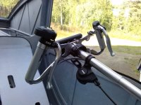
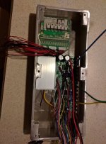
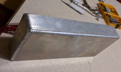
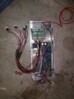
Got metal motorcycle handlebar controls for turn signals, horn, headlights, regen, reverse, cruise, etc. As well as a key ignition. Before I can wire them all up I gotta get the real nice marine electrical connectors in the mail on monday as well as finish up the enclosed electrical box I made today that will house the BMS, controller, step down converter, and fuse bus. EVERYTHING is getting a fuse. I don't trust this chinese shit, especially after having the 100.8v charger transistor fail in the first 30 minutes. Wish there was some good competition made with good components.

IMG_20160805_225558zzz.jpg
IMG_20160805_225633.jpg


Don't worry, the BMS heatsinks will be tied into the 1/4" thick walls of the enclosure. Hope the walls can dissipate the heat well enough that I don't have to install a fan or heatsink fins.
 
tahustvedt said:
I have used the same levers since the beginning, but they are road time trial levers, which have a shorter cable pull than mtb levers so they need road calipers to work well.
YOu can get a pulley from Problem Solvers to fix that, IIRC.
 
nerdalert said:
Wish there was some good competition made with good components.
Does http://ebikes.ca carry any of the stuff you're after?
 
2016-08-11-21-52-29-768x1024.jpg

The tube walls are machined thin. Maybe a pound? I could have trimmed it up and made it light but it's a prototype. Never wanna put hours into something and then redo it. The steering kingpin shafts are going to be redone next week and the bearings replaced with lighter options. 15 pound savings perhaps
 
The pedals are all chained up and it now functions as a bicycle. I didn't bother putting in derailleurs because on the next version I'll be using an internally geared hub (NuVinci)

Finishing the wiring and fusing tomorrow so that once the body is done it is as simple as popping in the fuse for each light system, horn, etc.

View attachment 1

Every board in the box is electrically insulated from the box. The walls were used as heatsinks for the transistors on the BMS, voltage converter, and controller. 3M insulated thermally conductive tape was used to insulate the drain/flange of the transistors from the box. Will monitor internal temperature in case it wants to overheat. Fan can be added but when the body is done I will mount all the components in their original boxes inside the body.

IMG_20160821_205210.jpg

Both the batteries and the electronics will be mounted temporarily during the skeleton testing phase until the body is built which will give me a great deal more mounting points. Not doing any testing in the wet to keep it clean and protect the electronics.

Will be testing it out this week while I build replacement front spindles for the more heavy duty front wheels and tires with the 20mm thru axles with cartridge bearings. Bronze lower bearings with rubber compression bushings will replace the lower flange mount bearings and the upper bearings will be replaced with either bronze or a plastic type bushing. A great deal of weight will be coming off the front end. Perhaps 15 pounds.

In case anyone was wondering, the turning radius is well inside a single lane of street. (less than 12 feet)
 
Back
Top