Nanotech LiPo booster pack for my GEM e4...

Hi Gary,

Thanks for the idea (bought a ZENN):
http://endless-sphere.com/forums/viewtopic.php?f=34&t=29580&p=427014#p427014
Mitch bought the 2006 ZENN for $2,550

Here are some packs sold for GEM, ZENN etc. Don't like the prices but they have range estimates. About 170wh per mile which seems reasonable.

For comparison the ZENN batteries are 6 x 73 lbs = 438 lbs
Lithium 72v Conversion Pricing 60Ah
Kwh Capacity 4.61
Pack Weight 132.24
Range @ Installation 27

Lithium 72v Conversion Pricing - 70 Ah
Kwh Capacity 5.38
Pack Weight 123.6
Range @ Installation 31.5

Lithium 72v Conversion Pricing - 100Ah
Kwh Capacity 7.68
Pack Weight 185.28
Range @ Installation 45.00
 
That's great news about your Zenn. :) You got a great deal, I think. I paid like 2-1/2 times that for my 2007 GEM.

I've been busy lately, and haven't had too much time to test my booster pack. I ended up frying the FETs the first time I gunned it off the line, after installing the new 15Ah "boxed" version. On the original 10Ah variant, I had used six FETs, but the output terminal bolt was attached directly through the PCB. On the new one, I used a copper strap, bent 90 degrees, to go from the negative terminal bot on the end plate, to the side-mounted PCB. This was simple plated "strapping", and is a lousy conductor. Even minutes after I heard the telltale "pffft", and I undid the end plate, the negative bolt and the strap were still extremely hot. I think what happened is that due to too much resistance, everything got too hot, including the FETs, which did not have much in the way of a heat sink.

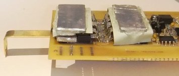
After removing the failed FETs, and cleaning things up, I installed new FETs, but doubled the number, organizing them in double-decker form. I then sandwiched aluminum heatsink bars in between the tabs, added a layer of kapton tape to the top and then fit one more piece of aluminum to each set of four FETs. These two pieces make physical contact with the metal box.

GEM Booster Pack-42.jpg

To connect the PCB to the negative bolt on the end plate, I used a solid brass link, which should handle the current a lot better than the cheap plated steel strap I was using before.

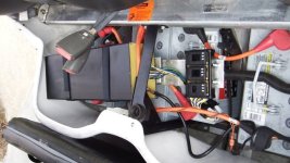
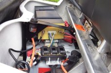
Anyway, the 15Ah booster pack is back on the GEM, and I've done a few quick tests, just to make sure it can handle the power now (it does...), but I haven't had time to do any range tests just yet. I'm hoping to get to this next week.

GEM Booster Pack-43.jpg
GEM Booster Pack-44.jpg


Once I know how much of a range boost I really get, I'll have a better idea about how much capacity I'd need for a full Lithium-based gel replacement.

-- Gary
 
GGoodrum said:
I've been busy lately, and haven't had too much time to test my booster pack. I ended up frying the FETs the first time I gunned it off the line, after installing the new 15Ah "boxed" version. On the original 10Ah variant, I had used six FETs, but the output terminal bolt was attached directly through the PCB. On the new one, I used a copper strap, bent 90 degrees, to go from the negative terminal bot on the end plate, to the side-mounted PCB. This was simple plated "strapping", and is a lousy conductor. Even minutes after I heard the telltale "pffft", and I undid the end plate, the negative bolt and the strap were still extremely hot. I think what happened is that due to too much resistance, everything got too hot, including the FETs, which did not have much in the way of a heat sink.


This is because any FET mounted to a PCB is going to fail. :) SMT power electronics = Fail. :)


Your application is just SCREAMING for some TO-247 fets. 2-3 of them on a heatsink (and the heatsink would be the drain tab connection) would be so neat and tidy and reliable.
 
liveforphysics said:
This is because any FET mounted to a PCB is going to fail. :) SMT power electronics = Fail. :)


Your application is just SCREAMING for some TO-247 fets. 2-3 of them on a heatsink (and the heatsink would be the drain tab connection) would be so neat and tidy and reliable.

Actually, these are eight TO-220-based 4110s, which have metal tabs and these tabs make metal-to-metal contact with the aluminum "sandwich" bars, and the metal case. I hear you, though, about the TO-247s The next iteration I do will definitely use thes in place of the 4110s. :)

-- Gary
 
Hi Gary,

Where are your range results?

When you go all Lithium (Gem is probably the same or similar):
ZENN tech support said:
The battery charger is a programmable DeltaQ charger, which, depending on your battery choice, will need to be re-programmed to a suitable charging algorithm.
What someone told me, haven't got the manual or contacted DeltaQ yet is you disconnect the charger from the pack, plug it in to AC and there is a way to select a set of settings. So you might be able to find a better profile when you dump the Gels.

http://www.endless-sphere.com/forums/viewtopic.php?f=14&t=26072&start=315#p424869
liveforphysics said:
All the DIY'ers in the USA all buying A123 and only A123 wouldn't make up for the damage a single lawsuit from a single idiot who injures/burns-down someone/something with A123's products.

Gary said:
In any case, I think the "regular" Turnigy's we've all been using will be fine, especially if they in an enclosed metal box. As suggested, I'm going to add a pressure vent plug, that will vent any overpressure down away from anything that could burn. I'm also going to be monitoring the charge and discharge cycles for awhile, to get a good idea of how well the cells are behaving. Later I'll just check them once in awhile, to see how they are doing. It's pretty easy to spot cells starting to go hinky, if you monitor a cycle once in awhile.
Luke might be exaggerating but IMO HK Lipo is probably fine for you but I'd be very careful selling them!
 
If and when I ever decide to go all Lithium, I'll probably go with a pack based on the 20Ah a123 pouch cells. At that time, I'll look at maybe re-programming the DeltaQ charger. For now, though, the existing profile works just fine. The basic CV point is 82.8V, which works out to 4.14V per cell. It takes a long time for the 100Ah gels to get to this point, so there's a lot of time to do cell balancing on the LiPLos.

I actually have my booster pack apart again, so I still don't have a definitive number on the range improvement. Best guess at this point is about 25miles, vs. about 13-14. Anyway, the pack is apart because I'm still not happy about how much heat is generated with the current charge control setup. The negative terminal is still getting quite hot. I think this is because the brass strap I'm using between the FETs and the negative terminal is still not big enough to handle 200A+. With my original prototype setup, the FET board was in the front and the negative terminal bolt went through the PCB. I've got a new layout I just did that goes back to that style, with a front-mounted board, with a new cover in front of it, so that I can have the negative terminal bolt directly to the FET/charge control board.

I'm also going to use the "Lite" variant of the cell circuits. These have shunts that pass about 170mA of current, instead of the 600-700mA with the previous board. This means it will take a bit longer to balance, but like I said, there lots of time for this, while the gels are still in the CC phase. This means there will be no heat to speak of, inside the box.

I should get the new board Tuesday, so I hope to get this back into the GEM by the end of next week.

-- Gary
 
Back
Top