chelsealuttrall
1 mW
- Joined
- Jan 31, 2021
- Messages
- 15
I'm a beginner when it comes to playing with electricity--but I like it a lot. I'm attempting to convert an old moto to electric and have been working on it for a while. I've been stuck for the last year (obviously, I don't work on it very often), but I'm tired of not knowing what to do to get past this road block.
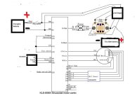
I have a QS Motor (16" Hub Motor Brushless Non Gear 72V 6kW), Kelly Controller (Kelly KLS-8080H), and AegisBattery (72V 20Ah Lithium Battery with Charger). I have a Tyco Contactor (Tyco 100 Amp 12V Relay / Contactor / Solenoid LEV100 KILOVAC).
Previously, I had it wired correctly (I thought...but obviously not), and I turned it on. The first time I turned it on, the contactor "clicked" and the voltage screen on the throttle was on. But, then, it slowly (like within a minute or two) burned my fuse and stopped working. After that, I kept trying and I blew a fuse instantly every time when I turned the key. I reworked the wiring again, thinking that I just had it wired incorrectly....
Since then, though, I can't get any current past my contactor. My battery is working fine. And current is getting to my contactor. But, it's not doing anything...whether I turn keys or anything, it just sits there. And I REALLY think I have the wiring correct, according to the diagrams....
Any tips on where to go next with troubleshooting? I'm kind of at a loss.
--chelsea
") and completely draw your own from scratch, traced out from what you *actually* have wired.
and completely draw your own from scratch, traced out from what you *actually* have wired. 
![HTB1.1J4QpXXXXa7apXXq6xXFXXXV[1].jpg](/sphere/data/attachments/158/158473-d15779c93a34571a69dbf17a83bf2ba2.jpg)