New 16-cell Battery Management System (BMS)

albie said:
not sure if you saw what i posted in the other thread about the duct tape packs but...

would these bms be able to handle 2x 48v packs connected in series to make a 96v pack?

I'd have to check with Bob on this, but I think so. It depends on the high-end voltage rating for the FETs and some of the other parts. Certainly using two complete boards, one for each 48V "half", would work fine.

-- Gary
 
fechter said:
Gary: one feature I've seen on the fancier BMS systems is a provision to drop the charging current low if any of the cells is below the low voltage threshold. If you had a discharged pack that sat around long enough to self-discharge, some cells could be that low. Apparently the cells can be damaged by full charging current if they are too low.

Any thoughts?

I'd have to think about this, to see if it is really needed, as the amount of current that a TC54 chip draws in standby is about a few microamps. It would take years to discharge a LiFePO4-based pack. Nonetheless, I think it would be easy enough to do with what we have, because we are already doing current limiting once the shunts start conducting.'ll talk to Bob about this. Maybe we can get it into the next version.

We are still making a few last minute tweaks to the current limit function. I would like to not have to use a pot, to adjust the limit to 1A, but because of parts tolerance issues, the range right now can be from .5A to 1.5A. Using a pot is not a big deal, but it complicates the checkout/test procedure. If we can do it without a pot, it will be a lot easier.

One way, or another, I hope to have the testing done today. :) Once the design is pretty stable, we'll publish the schematic here, along with Bob's "theory of operation" document he's been updating, as we go.

-- Gary
 
GGoodrum said:
fechter said:
Gary: one feature I've seen on the fancier BMS systems is a provision to drop the charging current low if any of the cells is below the low voltage threshold. If you had a discharged pack that sat around long enough to self-discharge, some cells could be that low. Apparently the cells can be damaged by full charging current if they are too low.

Any thoughts?

I'd have to think about this, to see if it is really needed, as the amount of current that a TC54 chip draws in standby is about a few microamps. It would take years to discharge a LiFePO4-based pack. Nonetheless, I think it would be easy enough to do with what we have, because we are already doing current limiting once the shunts start conducting.'ll talk to Bob about this. Maybe we can get it into the next version.


i did consider this, but the board was getting pretty crowded and we did not think it would be a big issue unless people leave their packs on the shelf for months. all it would take is another transistor to activate the shunt for any cell when its isolator activates on low voltage. the design already limits the charge current when any shunt is active, so that would let the cell come up at a current of an amp or so until it rises above the .150v hysteresis level of 2.25v at which time it would release the lvc signal and restore the full charge current. If there is enough interest we will go to surface mount and then there will be plenty of room for this function. After a bit of thought, it should not take more than a transistor, resistor, and a couple of diodes to do the whole string, if we use the summed lvc signal to cut down the charge current after separating it out so it does not do this when the charger is not connected.

We are still making a few last minute tweaks to the current limit function. I would like to not have to use a pot, to adjust the limit to 1A, but because of parts tolerance issues, the range right now can be from .5A to 1.5A. Using a pot is not a big deal, but it complicates the checkout/test procedure. If we can do it without a pot, it will be a lot easier.

because we are using only a .005 ohm current measuring shunt to keep power dissipation down to regulate the current at an amp requires a servo loop that works at 5 mv. The LM358 used has a fairly low input offset of 2-3 mv but this could still result in an uncertainty of .5A in the charge regulation loop. Not quite good enough when you want 1A. A pot is going to be pretty unavoidable, as there are just not very many good op amps that run on single supply and have the offset characteristics needed for accuracy without a pot. adjusting the current should be easy enough for anyone capable of reading the voltage across a resistor of 5 mv accurately.

One way, or another, I hope to have the testing done today. :) Once the design is pretty stable, we'll publish the schematic here, along with Bob's "theory of operation" document he's been updating, as we go.

I know it has been a bit frustrating for Gary to get his board working with me helping just off and on but he has done well, and is having the same kind of problems arise we expect kit builders to experience, so we hope to prevent some of the possible assembly and test problems.
-
 
Odd question - is it worth it to patent your board before posting the schematic ?

Seems like y'all have put a lot of effort into it.

Weather is getting warmer here

DK
 
Deepkimchi said:
Odd question - is it worth it to patent your board before posting the schematic ?

Seems like y'all have put a lot of effort into it.

Weather is getting warmer here

DK
thanks but there is really nothing patentable there. it is just basic analog electronics and choosing the right components to do the job. we decided that we would see the schematic here anyway soon after the first kit was sold, so there was no point in trying to keep it a secret. i have no problem with people copying the design or parts of it. it is not built by somebody else because there are over $100 in parts in it even shopping for good prices. if gary can sell them and make 5 bucks he will be doing well. i hope you guys all appreciate his hard work. as for me i don't sleep anyway and i gotta do something...
 
Odd question - is it worth it to patent your board before posting the schematic ?

People seem to be patenting things that could never have been patented before. For example, in my field, someone got patent that covers any concrete that uses recycled old concrete in the mix (unless it is below some unusable compressive strength). The result? The beneficial re-use of old concrete was greatly reduced.

On my e-max's controller, not only are schematics not available, but the numbers were carefully scraped off all IC's used on the board. Fortunately, I also have an older controller where this wasn't done.
 
I, for one, REALLY appreciate Gary and Bob's efforts. I think you guys are filling perhaps our most iportant issue. I have ideas on this myself, and I'm looking forward to seeing how you guys do it. I don't care too much about who comes up with a good solution, or who gets credit. I'd just like to see it get done.

I encountered the problem of one of my cells going bad when my overall voltage was fine. WHen I got home, the bad cell was 0.9v.

I'm going to look to see if you guys have posted the schematic.

I will gladly share any ideas with you guys.
 
I used to hear patent lawyers say that a patent is worth what you're willing to spend to defend it. You can end up ruining your enterprise in legal fees, and often the infringer just files for bankruptcy protection if you win.
 
Yeah, a patent wouldn't be worth the trouble. About all we will do is maybe copyright the documentation, mainly to keep a manufacturer from lifting everything verbatim.

Bob is right, though, we are definitely not going to rich building and selling these. :) At this point, I'll be happy to break even at some point. If you buy the parts in small quantities, it is going to cost about $80. The boards will cost over $20 in small (<10...) quantities. I can save some by getting higher quantities, on everything, which is what I'm doing. I'm hoping to hold the kit price to just under $100. I think we will also now be able to offer an assembled and tested version, hopefully for not too much extra.

We finally finished up the testing and are now going through verifying the assembly and test procedures. This will be done today, hopefully. Kits should be available in the next day, or so. We will post the schematic here, in a little bit. I just need to clean up a couple of things.

-- Gary
 
Wooah, I've been out of the loop for a few months now :shock: :shock: . So what did I miss? :lol: :lol: j/k Man this is cool. So I can use this BMS with my Mastech PSU to charge my A123 16s5p pack and totally eliminate the Hyperion balancers I've been using ? And I don't have to sit there and make sure the Mastech doesn't overcharge my pack cuz the BMS will cut off the current? Nice. I hated waiting for the Mastech to hit 0.8mA to 1.0A before I can shut off the charge.

Since I also don't have a LVC board to protect my pack during discharge, your BMS will cover that for me too ? Nice. I think I still have some space in my rack bag.

Sorry, just had to make sure I was reading everything correct. This is what I've been waiting for.
 
There's no doubt that Gary and Bob's circuit will be great. There is also a rapidly growing market for this kind of thing, but nobody wants to sit around assembling these things (at least not anyone I know). Once the design gets ironed out and tested, it would be cool if somebody got a large batch of them built in a factory (by machines). If the quantity was large enough, the price would come down.

Anybody want to make an investment?

Any idea what it would cost to have them completely assembled?
For automated assembly, a surface mount component version would probably be cheaper.
There must be places that speciallize in doing this kind of work, but I don't know any...
 
DeeL2003 said:
Wooah, I've been out of the loop for a few months now :shock: :shock: . So what did I miss? :lol: :lol: j/k Man this is cool. So I can use this BMS with my Mastech PSU to charge my A123 16s5p pack and totally eliminate the Hyperion balancers I've been using ? And I don't have to sit there and make sure the Mastech doesn't overcharge my pack cuz the BMS will cut off the current? Nice. I hated waiting for the Mastech to hit 0.8mA to 1.0A before I can shut off the charge.

Since I also don't have a LVC board to protect my pack during discharge, your BMS will cover that for me too ? Nice. I think I still have some space in my rack bag.

Sorry, just had to make sure I was reading everything correct. This is what I've been waiting for.

yes, yes,thanks. the cell cutoff for charge can be adjusted from 3-4v with the standard values or by changing a resistor it could be anywhere from 2.5v-7v, and the lvc can be 2.1 or 2.7 or anything over 2.1 by adding a resistor pair to each channel

the mastech is probably the cheapest adjustable power supply around. i have the same one with a different name i use often. it will be necessary to have a variable power supply to test the board and adjust the shunts. i am including a link to a kit for $24 that runs 110v to 0-12v at 2A or a parts list and schematic to make a 0-12v 2A supply out of <$10 in radio shack parts that could be powered by your batteries, to use in adjusting the shunts and testing.
 
fechter said:
There's no doubt that Gary and Bob's circuit will be great. There is also a rapidly growing market for this kind of thing, but nobody wants to sit around assembling these things (at least not anyone I know). Once the design gets ironed out and tested, it would be cool if somebody got a large batch of them built in a factory (by machines). If the quantity was large enough, the price would come down.

Anybody want to make an investment?

Any idea what it would cost to have them completely assembled?
For automated assembly, a surface mount component version would probably be cheaper.
There must be places that speciallize in doing this kind of work, but I don't know any...

i believe these boards will take a trained assembler about 2 hours. i will try to keep the labor on assembled units at $30. we intend to go to smt after we get some feedback and make sure it does everything most people want. once it is smt the labor cost will go way down and we could have a batch made. this is all gary's area, i am only doing the design work. anybody wanting to invest in the bms can talk with him. if you want raw cells, i will sell them for $40 plus shipping in any quantity. i was previously not lowering the price to $40 unless people bought 16 cells. btw my cost is $35 + shipping to me, so i am basically giving them away to build a market and hoping the price will come down when more people start buying them.
 
DeeL2003 said:
Wooah, I've been out of the loop for a few months now :shock: :shock: . So what did I miss? :lol: :lol: j/k Man this is cool. So I can use this BMS with my Mastech PSU to charge my A123 16s5p pack and totally eliminate the Hyperion balancers I've been using ? And I don't have to sit there and make sure the Mastech doesn't overcharge my pack cuz the BMS will cut off the current? Nice. I hated waiting for the Mastech to hit 0.8mA to 1.0A before I can shut off the charge.

Since I also don't have a LVC board to protect my pack during discharge, your BMS will cover that for me too ? Nice. I think I still have some space in my rack bag.

Sorry, just had to make sure I was reading everything correct. This is what I've been waiting for.

If the Mastech will go up to about 16 x 3.65V + about .5V, then yes, this will work fine. The BMS does include the LVC function, and has two 4110 FETs to do active cutoff of the negative power lead if triggered.

-- Gary
 
As Bob says, we can do an SMT version, but we'll wait a bit and see if there really is a demand. This would get the cost down.

For now, for those wanting fully assembled and tested versions, Bob will do them. If the demand gets too high, we'll look for some other intermediate options. We have looked into having htem assembled in Mexico, for instance, using the existing layout.This could save a decent amount of cost, as a lot of the parts are made down there now anyway.

-- Gary
 
Count me in on one of the pre-assembled and tested BMS. I'm too solder and electronically-challenged. I hope you'll offer them soon after your kits are released. BTW, how do I go about connecting the BMS to my existing pack. Pics can be found here: http://endless-sphere.com/forums/viewtopic.php?f=14&t=2317. Do I have to take it all apart or can I use my existing Hyperion and powerpole connectors?

About the Mastech, I have the 5020 model so I had to charge each 8s5p separately. So does that mean I need two BMS's since I can't charge a whole 16s together?

Thanks for the quick reply guys.
 
DeeL2003 said:
Count me in on one of the pre-assembled and tested BMS. I'm too solder and electronically-challenged. I hope you'll offer them soon after your kits are released. BTW, how do I go about connecting the BMS to my existing pack. Pics can be found here: http://endless-sphere.com/forums/viewtopic.php?f=14&t=2317. Do I have to take it all apart or can I use my existing Hyperion and powerpole connectors?

About the Mastech, I have the 5020 model so I had to charge each 8s5p separately. So does that mean I need two BMS's since I can't charge a whole 16s together?

Thanks for the quick reply guys.

Yes, I remember this. You can definitely use the existing Hyperion connectors. You just need to have matching plugs that can attach to the BMS board(s). You need to either break the main power lead connections, and insert the board in between, or just add Powerpoles to the BMS input wires, and plug into the ones coming from the pack. The board has separate output connections so you can simply run wires from these with two more Powerpole connectors. There are also two separate charger + and charger - connections, so a separate set of charger wires are used.

Although with a different supply only one board would be required, you could do this with two boards, each populated with half the channels, and charge each half separately, like you are doing now.

-- Gary
 
DeeL2003 said:
Count me in on one of the pre-assembled and tested BMS. I'm too solder and electronically-challenged. I hope you'll offer them soon after your kits are released. BTW, how do I go about connecting the BMS to my existing pack. Pics can be found here: http://endless-sphere.com/forums/viewtopic.php?f=14&t=2317. Do I have to take it all apart or can I use my existing Hyperion and powerpole connectors?

About the Mastech, I have the 5020 model so I had to charge each 8s5p separately. So does that mean I need two BMS's since I can't charge a whole 16s together?

Thanks for the quick reply guys.

if your supply is 50v 20A it probably goes to 51-52v so you need another 8v or so. i have some 3.3v 20A switching modules that are isolated and can thus be put in series with your supply output to raise it up by 4.5v each so two of those would get you up to 59-60v and they would also be powered by your mastech supply, so you could still easily provide the 8A charge current limit of the bms. these supplies are about 1" x 2" x 1/4" each rated 66w. they list in digikey for $169 but you can get them new for $10 at http://tinyurl.com/2b7ayo the supplies have trim and sense inputs that can be used to limit current and raise voltage to at least 4.5v. they are also good as single cell chargers where one 48v system can power each to exactly 3.65v and thus safely charge at up to 20A. i have used 16 of them powered by a 1200w 48v supply and i can charge my lifebatt pack in 1/2 hour. Two of these in series with your supply output will get your supply up to 60v. there are no connectors supplied but if we are building it for you we could do a custom version for a few bucks extra with the proper connectors.
 
GGoodrum said:
DeeL2003 said:
Count me in on one of the pre-assembled and tested BMS. I'm too solder and electronically-challenged. I hope you'll offer them soon after your kits are released. BTW, how do I go about connecting the BMS to my existing pack. Pics can be found here: http://endless-sphere.com/forums/viewtopic.php?f=14&t=2317. Do I have to take it all apart or can I use my existing Hyperion and powerpole connectors?

About the Mastech, I have the 5020 model so I had to charge each 8s5p separately. So does that mean I need two BMS's since I can't charge a whole 16s together?

Thanks for the quick reply guys.

Yes, I remember this. You can definitely use the existing Hyperion connectors. You just need to have matching plugs that can attach to the BMS board(s). You need to either break the main power lead connections, and insert the board in between, or just add Powerpoles to the BMS input wires, and plug into the ones coming from the pack. The board has separate output connections so you can simply run wires from these with two more Powerpole connectors. There are also two separate charger + and charger - connections, so a separate set of charger wires are used.

Although with a different supply only one board would be required, you could do this with two boards, each populated with half the channels, and charge each half separately, like you are doing now.

-- Gary

Yeah I tried getting Mike to find me a set of matching 7 pin Hyperion connectors a while back, but it proved more difficult than expected. The only matching set came from the Hyperion balancer itself and it's already pre-installed. Can't find them loose. I hope there's a simple way around this.

About the BMS, I think getting 2 would be too much cost-wise. Is there any way to just have one 8s pack connected to the BMS,then to the PSU and charge separately? And when it's time to ride, connect both packs to the BMS? If not, I'll go with Bob's idea.
 
bobmcree said:
DeeL2003 said:
Count me in on one of the pre-assembled and tested BMS. I'm too solder and electronically-challenged. I hope you'll offer them soon after your kits are released. BTW, how do I go about connecting the BMS to my existing pack. Pics can be found here: http://endless-sphere.com/forums/viewtopic.php?f=14&t=2317. Do I have to take it all apart or can I use my existing Hyperion and powerpole connectors?

About the Mastech, I have the 5020 model so I had to charge each 8s5p separately. So does that mean I need two BMS's since I can't charge a whole 16s together?

Thanks for the quick reply guys.

if your supply is 50v 20A it probably goes to 51-52v so you need another 8v or so. i have some 3.3v 20A switching modules that are isolated and can thus be put in series with your supply output to raise it up by 4.5v each so two of those would get you up to 59-60v and they would also be powered by your mastech supply, so you could still easily provide the 8A charge current limit of the bms. these supplies are about 1" x 2" x 1/4" each rated 66w. they list in digikey for $169 but you can get them new for $10 at http://tinyurl.com/2b7ayo the supplies have trim and sense inputs that can be used to limit current and raise voltage to at least 4.5v. they are also good as single cell chargers where one 48v system can power each to exactly 3.65v and thus safely charge at up to 20A. i have used 16 of them powered by a 1200w 48v supply and i can charge my lifebatt pack in 1/2 hour. Two of these in series with your supply output will get your supply up to 60v. there are no connectors supplied but if we are building it for you we could do a custom version for a few bucks extra with the proper connectors.


Email sent
 
Somehow one of my posts went into the ozone somewhere.

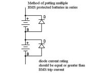
Anyway, if you wanted to run multiple packs with BMS in series, you would put diodes across each one like this:
BMS in series config.jpg

This way, if any BMS goes open circuit, the entire pack voltage is not across the switch, just the normal pack voltage (plus one diode drop). This scheme would be useful if you wanted to run voltages higher than the BMS was rated for. This will also work with other styles of BMS.
 
Okay, we finally finished the testing, and everything seems pretty rock solid. I've built up two new boards, using the newest assembly and test instructions, and with a couple more tweaks, it will be ready-to-go.

Here is the final schematic:

LiFeCycle%20BMS-v1%2012a.png


Bob wrote up a very good "theory of operation", which also includes a more easily readable schematic. It can be found here LiFeCycle BMS Description

One of the last changes we got in was Richard's suggestion about throttling back the charge current if any of the cells are too low (i.e. -- below 2.1V...). It turns out this simply required adding one more inexpensive NPN transistor.

We made a couple of changes to the layout, so I'm having another run done. I will have these back by Thursday. For the assembled and tested versions, we can use the existing boards, as it just requires a couple additions, mainly that make use of existing vias. The bottomline is we can probably make the assembled versions available starting tomorrow or Wendesday, and the kits by Friday. It will take about a week for the assembly and test for those versions

Here's what the PCB looks like:

LiFeCycle%20BMS-v1%2012%20PCB.png


It is pretty busy, mainly because we weren't ready to switch to surface mount, just yet, and because I wanted to keep this to the same 3" x 6" form factor, so that it will fit on front of a LiFeBatt pack.

Once I get the assembly and test procedures done we should be pretty much done. I still have some work to do on the heat sinks, but I'm hoping to finish up these tomorrow. These will be optional for the kits and the assembled versions, as there are lots of choices for these, depending on the installations.

Anyway, once we get these going, I will then also start offering LiFeBatt packs with integrated BMS units. I also just worked a deal with Soneil, so we will also be able to offer 36V and 48V versions of their excellent SRF series of chargers, with "tweaked" outputs to perfectly match the BMS.

-- Gary
 
Yep, that there scheematic looks right to me! :wink: j/k

Wow! I cannot believe what you guys are able to come up with. This is very impressive indeed. It's way over my head, but still, I can be impressed by it.

I think you guys should take your wives out to dinner and a glass or two of wine since you are tinkering too much! :p
 
Great job Bob and Gary! My pack is A123 M1, 16s12p, at 8 amps, how long do you think it would charge from complete depletion? What end of charge voltage measurement with no load should I expect to set it for?

Jeff K./Deep Cycle
 
jeffkay said:
Great job Bob and Gary! My pack is A123 M1, 16s12p, at 8 amps, how long do you think it would charge from complete depletion? What end of charge voltage measurement with no load should I expect to set it for?

Jeff K./Deep Cycle

Hey Jeff --

16s12p? Yipes! :shock: That is some serious Wh. :D

Let's see, 12 x 2.3 Ah is 27.6 Ah. Charging at a 1C rate would require 27.6A of charge current to recharge a depleted pack in one hour, so at an 8A rate, it would take about 3-1/2 hours.

I'm not sure what you mean in your second question.

-- Gary
 
Back
Top